ASROCK G41M-LE User Manual
Hide thumbs
Also See for G41M-LE:
- Specifications (1 page) ,
- User manual (47 pages) ,
- User manual (118 pages)

Related Manuals for ASROCK G41M-LE


Summary of Contents for ASROCK G41M-LE
-
Page 1: User Manual
G41M-LE User Manual Version 1.0 Published October 2008 Copyright©2008 ASRock INC. All rights reserved. 1 1 1 1 1... - Page 2 (including damages for loss of profits, loss of business, loss of data, interruption of business and the like), even if ASRock has been advised of the possibility of such damages arising from any defect or error in the manual or product.
-
Page 3: Table Of Contents
1.2 Specifications ..............6 1.3 Minimum Hardware Requirement for Full HD 1080p Blu-ray (BD) / HD-DVD Playback Support ...... 10 1.4 Passed Full HD 1080p Blu-ray (BD) / HD-DVD Films in Our Lab Test ..............10 1.5 Motherboard Layout ............11 1.6 I/O Panel ................. - Page 4 3.5 Hardware Health Event Monitoring Screen ...... 43 3.6 Boot Screen ..............44 3.5.1 Boot Settings Configuration ........44 3.7 Security Screen .............. 45 3.8 Exit Screen ..............46 4 Software Support 4 Software Support .......... 4 Software Support ..........
-
Page 5: Introduction
ASRock’s commitment to quality and endurance. In this manual, chapter 1 and 2 contain introduction of the motherboard and step-by-step guide to the hardware installation. Chapter 3 and 4 contain the configuration guide to BIOS setup and information of the Support CD. -
Page 6: Specifications
Specifications Specifications 1 . 2 1 . 2 Specifications Specifications Platform - Micro ATX Form Factor: 9.6-in x 8.6-in, 24.4 cm x 21.8 cm ® - LGA 775 for Intel Core 2 Extreme / Core 2 Quad / Core ®... - Page 7 - HD Audio Jack: Side Speaker/Rear Speaker/Central/Bass/ Line in/Front Speaker/Microphone (see CAUTION 9) Connector - 4 x SATAII 3.0 Gb/s connectors (No Support for RAID and “Hot Plug” functions) (see CAUTION 10) - 1 x ATA100 IDE connector (supports 2 x IDE devices)
-
Page 8: Passed Full Hd 1080P Blu-Ray (Bd) / Hd-Dvd Films In Our Lab Test
Overclocking may affect your system stability, or even cause damage to the components and devices of your system. It should be done at your own risk and expense. We are not responsible for possible damage caused by overclocking. - Page 9 10. Before installing SATAII hard disk to SATAII connector, please read the “SATAII Hard Disk Setup Guide” on page 25 to adjust your SATAII hard disk drive to SATAII mode. You can also connect SATA hard disk to SATAII connector directly.
-
Page 10: Minimum Hardware Requirement For Full Hd 1080P Blu-Ray (Bd) / Hd-Dvd Playback Support
VD Playback Suppor VD Playback Suppor VD Playback Suppor t t t t t Full HD 1080p Blu-ray (BD) / HD-DVD playback support on this motherboard requires the proper hardware configuration. Please refer to below table for the minimum hardware requirement. -
Page 11: Motherboard Layout
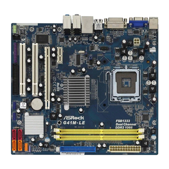
BIOS SPI Chip FSB3 Jumper USB 2.0 Header (USB6_7, Blue) 775-Pin CPU Socket USB 2.0 Header (USB4_5, Blue) 2 x 240-pin DDR2 DIMM Slots Clear CMOS Jumper (CLRCMOS1) (Dual Channel: DDRII_1, DDRII_2; Yellow) Floppy Connector (FLOPPY1) ATX Power Connector (ATXPWR1) -
Page 12: I/O Panel
Front Speaker (Lime) If you use 2-channel speaker, please connect the speaker’s plug into “Front Speaker Jack”. See the table below for connection details in accordance with the type of speaker you use. TABLE for Audio Output Connection Audio Output Channels Front Speaker Rear Speaker... -
Page 13: Installation
Chapter 2: Installation Chapter 2: Installation This is a Micro ATX form factor (9.6" x 8.6", 24.4 x 21.8 cm) motherboard. Before you install the motherboard, study the configuration of your chassis to ensure that the motherboard fits into it. -
Page 14: Cpu Installation
Before you insert the 775-LAND CPU into the socket, please check if the CPU surface is unclean or if there is any bent pin on the socket. Do not force to insert the CPU into the socket if above situation is found. - Page 15 PnP cap to assist in removal. 1. It is recommended to use the cap tab to handle and avoid kicking off the PnP cap. 2. This cap must be placed if returning the motherboard for after service.
-
Page 16: Installation Of Heatsink And Cpu Fan
CPU and the heatsink to improve heat dissipation. Ensure that the CPU and the heatsink are securely fastened and in good contact with each other. Then connect the CPU fan to the CPU_FAN connector (CPU_FAN1, see page 11, No. -
Page 17: Installation Of Memory Modules (Dimm)
DIMMs or the system components. Step 1. Unlock a DIMM slot by pressing the retaining clips outward. Step 2. Align a DIMM on the slot such that the notch on the DIMM matches the break on the slot. notch break... -
Page 18: Expansion Slots (Pci And Pci Express Slots)
2.6 Expansion Slots (PCI and PCI Express Slots) 2.6 Expansion Slots (PCI and PCI Express Slots) There are 2 PCI slots and 2 PCI Express slots on this motherboard. PCI slots: PCI slots are used to install expansion cards that have the 32-bit PCI interface. PCIE slots: PCIE1 (PCIE x1 slot) is used for PCI Express cards with x1 lane width cards, such as Gigabit LAN card, SATA2 card, etc. -
Page 19: Jumpers Setup
To clear and reset the system parameters to default setup, please turn off the computer and unplug the power cord from the power supply. After waiting for 15 seconds, use a jumper cap to short 2 pins on CLRCMOS1 for 5 seconds. - Page 20 When you mount a FSB800 or FSB1066 CPU, and try to overclock to FSB1333 (by BIOS setting) you may face the problem, that DRAM frequency will be overclocked very high. Please use jumper to force NB to be strapped at higher frequency, so the DRAM can work at lower frequency.
-
Page 21: Onboard Headers And Connectors
(see p.11 No. 22) FLOPPY1 Pin1 the red-striped side to Pin1 Note: Make sure the red-striped side of the cable is plugged into Pin1 side of the connector. Primary IDE connector (Blue) (39-pin IDE1, see p.11 No. 8) IDE1 PIN1... - Page 22 OUT2_L J_SENSE OUT2_R MIC2_R MIC2_L 1. High Definition Audio supports Jack Sensing, but the panel wire on the chassis must support HDA to function correctly. Please follow the instruction in our manual and chassis manual to install your system.
- Page 23 Though this motherboard provides 4-Pin CPU fan (Quiet Fan) support, the 3-Pin CPU fan still can work successfully even without the fan speed control function. If you plan to connect the 3-Pin CPU fan to the CPU fan connector on this motherboard, please connect it to Pin 1-3.
- Page 24 Though this motherboard provides 24-pin ATX power connector, it can still work if you adopt a traditional 20-pin ATX power supply. To use the 20-pin ATX power supply, please plug your power supply along with Pin 1 and Pin 13.
-
Page 25: Sataii Hard Disk Setup Guide
Before installing SATAII hard disk to your computer, please carefully read below SATAII hard disk setup guide. Some default setting of SATAII hard disks may not be at SATAII mode, which operate with the best performance. In order to enable SATAII function, please follow the below instruction with different vendors to correctly adjust your SATAII hard disk to SATAII mode in advance;... -
Page 26: Installation
STEP 2: Connect the SATA power cable to the SATA / SATAII hard disk. STEP 3: Connect one end of the SATA data cable to the motherboard’s SATAII connector. STEP 4: Connect the other end of the SATA data cable to the SATA / SATAII hard disk. 2 . 1 1 2 . -
Page 27: Introduction
Power-On-Self-Test (POST) to enter the BIOS SETUP UTILITY, otherwise, POST will continue with its test routines. If you wish to enter the BIOS SETUP UTILITY after POST, restart the system by pressing <Ctl> + <Alt> + <Delete>, or by pressing the reset button on the system chassis. -
Page 28: Navigation Keys
3 . 2 3 . 2 3 . 2 Main Screen Main Screen Main Screen When you enter the BIOS SETUP UTILITY, the Main screen will appear and display the system overview. BIOS SETUP UTILITY Smart Advanced H/W Monitor Boot... -
Page 29: Smart Screen
3.3 Smart Screen Smart Screen Smart Screen Smart Screen Smart Screen In the Smart screen, you can load the BIOS setup according to your requirements. BIOS SETUP UTILITY Main Advanced H/W Monitor Boot Security Exit Smart Exit system setup Smart Settings after saving the changes. -
Page 30: Advanced Screen
Advanced Screen Advanced Screen Advanced Screen Advanced Screen In this section, you may set the configurations for the following items: CPU Configuration, Chipset Configuration, ACPI Configuration, IDE Configuration, PCIPnP Configuration, Floppy Configuration, SuperIO Configuration, and USB Configuration. BIOS SETUP UTILITY... - Page 31 This item should always be [Auto] for better system stability. Ratio Status This is a read-only item, which displays whether the ratio status of this motherboard is “Locked” or “Unlocked”. If it shows “Unlocked”, you will find an item Ratio CMOS Setting appears to allow you changing the ratio value of this motherboard.
-
Page 32: Chipset Configuration
Vista and want to enable this function, please set this item to [Enabled]. This item will be hidden if the current CPU does not support Intel (R) SpeedStep(tm) tech.. Please note that enabling this function may reduce CPU voltage and lead to system stability or compatibility issue with some power supplies. - Page 33 This controls the number of DRAM clocks for CH1 RCOMP ODT. Configuration options: Configuration options: [Auto], [1] to [63]. DRAM CH0 tRD This controls the number of DRAM clocks for CH0 TRD. Configuration options: Configuration options: [Auto], [0] to [30]. DRAM CH1 tRD This controls the number of DRAM clocks for CH1 TRD.
- Page 34 DVMT/FIXED Memory You are allowed to adjust the shared memory size in this item if you set DVMT Mode Select as [DVMT Mode]. Configuration options: [128MB], [256MB] and [Maximum DVMT]. The option [Maximum DVMT] only appears when you adopt the memory module with 1024MB or above.
- Page 35 [Auto]. GLTREF Voltage Use this to select GLTREF Voltage. Configuration options: [Auto], [0.67 x Vtt], [0.65 x Vtt], [0.63 x Vtt] and [0.615 x Vtt]. The default value of this feature is [Auto]. Intelligent Energy Saver Intelligent Energy Saver is a revolutionary technology that delivers unparalleled power savings.
-
Page 36: Acpi Configuration
Use this item to enable or disable Ring-In signals to turn on the system from the power-soft-off mode. PCI Devices Power On Use this item to enable or disable PCI devices to turn on the system from the power-soft-off mode. PS/2 Keyboard Power On Use this item to enable or disable PS/2 keyboard to turn on the system from the power-soft-off mode. -
Page 37: Ide Configuration
It allows you to select between [SATA 1, SATA 2, SATA 3, SATA 4], [SATA 1, SATA 3, IDE 1], and [IDE 1, SATA 2, SATA 4]. If it is set to [SATA 1, SATA 3, IDE 1], then SATAII_2, SATAII_4 will not work. Likewise, if it is set to [IDE 1, SATA 2, SATA 4], then SATAII_1, SATAII_3 will not work. - Page 38 [ARMD]: This is used for IDE ARMD (ATAPI Removable Media Device), such as MO. LBA/Large Mode Use this item to select the LBA/Large mode for a hard disk > 512 MB under DOS and Windows; for Netware and UNIX user, select [Disabled] to disable the LBA/Large mode.
-
Page 39: Pcipnp Configuration
Use this item to enable or disable the S.M.A.R.T. (Self-Monitoring, Analysis, and Reporting Technology) feature. Configuration options: [Disabled], [Auto], [Enabled]. 32-Bit Data Transfer Use this item to enable 32-bit access to maximize the IDE hard disk data transfer rate. 3.4.5 3.4.5 3.4.5 PCIPnP Configuration... -
Page 40: Floppy Configuration
Use this item to enable or disable floppy drive controller. Serial Port Address Use this item to set the address for the onboard serial port or disable it. Configuration options: [Disabled], [3F8 / IRQ4], [2F8 / IRQ3], [3E8 / IRQ4], [2E8 / IRQ3]. - Page 41 Parallel Port Address Use this item to set the address for the onboard parallel port or disable it. Configuration options: [Disabled], [378], and [278]. Parallel Port Mode Use this item to set the operation mode of the parallel port. The default value is [ECP+EPP].
-
Page 42: Usb Configuration
[Enabled] - Enables support for legacy USB. [Auto] - Enables legacy support if USB devices are connected. [Disabled] - USB devices are not allowed to use under legacy OS and BIOS setup when [Disabled] is selected. If you have USB compatibility issue, it is recommended to select [Disabled] to enter OS. -
Page 43: Hardware Health Event Monitoring Screen
Hardware Health Event Monitoring Screen Hardware Health Event Monitoring Screen In this section, it allows you to monitor the status of the hardware on your system, including the parameters of the CPU temperature, motherboard temperature, CPU fan speed, chassis fan speed, and the critical voltage. -
Page 44: Boot Screen
3.6 Boot Screen Boot Screen Boot Screen Boot Screen Boot Screen In this section, it will display the available devices on your system for you to config- ure the boot settings and the boot priority. BIOS SETUP UTILITY Main Smart... -
Page 45: Security Screen
3.7 Security Screen Security Screen Security Screen Security Screen Security Screen In this section, you may set or change the supervisor/user password for the system. For the user password, you may also clear it. BIOS SETUP UTILITY Main Smart Advanced... -
Page 46: Exit Screen
BIOS SETUP UTILITY. Discard Changes and Exit When you select this option, it will pop-out the following message, “Dis- card changes and exit setup?” Select [OK] to exit the BIOS SETUP UTILITY without saving any changes. Discard Changes When you select this option, it will pop-out the following message, “Dis-... -
Page 47: Install Operating System
4 . 2 . 4 4 . 2 . 4 C o n t a c t I n f o r m a t i o n C o n t a c t I n f o r m a t i o n...
Need help?
Do you have a question about the G41M-LE and is the answer not in the manual?
Questions and answers