Advertisement
Quick Links
1. PREFACE
1.1 Introduction
The heart of a pH measuring loop are the electrodes. Yokogawa
has designed a wide range of electrodes to ensure this heart
keeps beating under the most severe conditions. A high degree of
standardization makes it possible to mount any electrode in the
standard program of fittings. Color coded strips on electrode and
cable and clear identification of sensor specifications make incorrect
installation virtually impossible.
1.2 Unpacking and Checking
Upon delivery, unpack the sensor carefully and inspect it to ensure
it was not damaged during shipment. If damage is found, retain the
original packing materials and then immediately notify the carrier
and the relevant Yokogawa sales office.
Make sure the Model Code and Serial Number on the sensor are
the same as on the packing list. Also, check any option(s) that were
ordered are included and correct.
1.3 Warranty and Service
Yokogawa products and parts are guaranteed free from defects
in workmanship and material under normal use and service for a
period of (typically) 12 months from the date of shipment from the
manufacturer. Individual sales organizations can deviate from the
typical warranty period, and the conditions of sale relating to the
original purchase order should be consulted.
Damage caused by wear and tear, inadequate maintenance,
corrosion, or by the effects of chemical processes are excluded from
this warranty coverage. In the event of warranty claim, the defective
goods should be sent (freight paid) to the Service Department of the
relevant sales Organization for repair or replacement (at Yokogawa's
discretion).
The following information must be included in the letter accompany-
ing the returned goods:
• Model Code and Serial Number.
• Original Purchase Order and Date.
• Length of time in service and description of the process.
• Description of the fault and circumstances of the failure.
• Process/environmental conditions that may be related to the
failure of the sensor
• Statement as to whether warranty or non-warranty service is
requested.
• Complete shipping and billing instructions for return of material,
plus the name and phone number of a contact person that can be
reached for further information.
• Clean Statement
Returned goods that have been in contact with process fluids must
be decontaminated and disinfected prior to shipment. Goods should
carry a certificate to this effect, for the health and safety of our
employees. Material Safety Data sheets must be included for all
components of the process to which the sensor(options) have been
exposed.
1.4 Serial number
The Serial number is defined by nine (9) alphanumeric characters:
X
X
Production location
1
2
X
X
Year/Month code
3
4
X
X
X
X
X
Tracking number
5
6
7
8
9
Example:
N3T500034
Table 1: Production Year
Table 2: Month code
Year
Year code
Month
Month code
2023
Z
January
1
2024
1
February
2
2025
2
March
3
2026
3
April
4
2027
4
May
5
2028
5
June
6
2029
6
July
7
2030
7
August
8
2031
8
September
9
2032
9
October
A
2033
A
November
B
2034
B
December
C
2. General specifications
The specifications for the sensor are clearly shown on the type plate
attached to the electrode cap. For detailed specification please down-
load GS 12B06J01-E-E(24).
Remark: The glass resistance is given at 25ºC (each temperature
increase of 10ºC halves the resistance of the membrane).
3. Installation
3.1. Preparation for use
For accurate pH measurement a gel layer must be formed on the
glass membrane surface. For this reason the pH sensitive part of the
electrode should be soaked for 24 hours before the electrode is used.
When an electrode has been stored dry and you need to use it
immediately (there is no time for soaking), you may do so, but as a
result initial regular re-calibration will be required until the gel layer
is formed.
The electrode when dispatched has a protective cover cap filled with
0,04% HCI solution around the membrane which ensures you can use
the electrode immediately.
3.2. Mounting
The electrode must be fitted with an electrode cable (type WU20-PC..).
For the pH electrode please mark with a red strip.
The mounting of an electrode in a fitting should be carried out as
shown in the example figure 2 or 3.
The electrode fits any Yokogawa cable fitted with the standard nut of
which the dimensions are shown in figure 1. The nut can be ordered
under part number K1500DW.
Fig. 1. K1500DW (set of 12 cable nuts)
Fig. 2. With mounting
set FP20-12, FP20S12
Fig 3. Mounting PG13.5
for Y-CAP sensors
3.3. Compatibility
Generally, the glass electrode is used in conjunction with a reference
electrode (with yellow marking strip) and a temperature sensor (green
marking strip).
NOTE: For the best performance the reference system of both glass and
reference electrodes should be similar.
3.4. Calibration and buffering
To calibrate a pH sensor, two buffer solutions with known pH values are
required. It is recommended that one buffer solution have a value near
to pH 7.00 (ITP).
Depending on the process value to be measured, the second buffer
solution should be either acidic (below 7.00) or alkaline (above 7.00) area.
Normally, the IEC buffers (4.01, 6.87 and 9.18) are used. The following is
a very general 2-point calibration procedure.
1. Clean the sensor (deposits may be removed using a 5% (approximate)
solution of HCL).
2. Rinse the sensor thoroughly with clean (demi) water.
3. Immerse the sensor in the first buffer (6.87 pH is recommended).
4. Refer to appropriate Instrument Instruction Manual for Calibration
procedures (Auto; Manual; Sample, etc.)
5. Rinse sensor thoroughly with clean (demi) water.
6. Immerse the sensor in the second buffer (4.01 or 9.18 recommended).
During calibration the temperature compensation should be active. The
instrument automatically compensates temperature changes. After cali-
bration is complete replace or re-install the sensor into the process.
WARNING:
During buffering the liquid earth and the temperature compensation
must be connected. The temperature of the buffer solution must be with-
in the limits of the technical specification as indicated on the type plate.
3.5. Cleaning
When the sensitivity of the electrode has noticeably decreased, the
electrode must be cleaned with a suitable detergent.
a. Depositions of hydroxides, lime, iron hydroxide can be removed by
immersing the electrode in a diluted solution of hydrochloric acid and
then cleaning with water.
b. Depositions of oil and fat can be removed by means of hot water in
conjunction with domes-tic washing solution.
c. When the result is unsatisfactory a domestic abrasive may be used.
d. Albuminous depositions can be removed by means of a solvent
containing: 8,5 ml concentrated hydroxide acid, 10 gr pepsin and 1 l
demi water.
NOTE: When polar solvents are used for special cleaning purposes, it is
necessary to soak the electrode for some time after cleaning as the polar
solvent influences the gel layer. When an a-polar solvent is used (ben-
zine, ethere, toluene) follow up treatment with a polar solvent (methanol,
acetone) and soaking is necessary.
3.6. Storage
Electrodes which are not in use for a longer period of time should be
removed and stored in 'wet pocket' filled with solution to prevent drying
out of the measuring elements.
3.7. Degraded electrodes
During measurement the glass membrane of the electrodes is affected.
This has one or more of the following effects:
a.
Decrease on the speed of response.
b.
Increase of the electrical resistance.
c.
Decrease of the sensitivity.
d.
Zero point shift.
The effect of aging of the electrodes makes it necessary to carry out
re-calibration of the electrode system regularly.
The frequency depends on the composition of the sample to be mea-
sured and the temperature, e.g.:
If the lifetime of an electrode is 100% at the room temperature, it will be
20% at 80ºC and only 5% at 120ºC.
It is possible to re-active an aged electrode by immersing it for 10
seconds in a P.V.C. beaker containing a solution of vinegar (1 mol) and
potassium fluoride (1 mol), ratio 1:1. After this the electrode must be
cleaned carefully.
WARNING:
As a result of the strong etching proporties of the acid, the handling
should be done carefully in consult with a security officer.
3.8. Isolation
Since the electrical resistance of the glass electrode is extremely high it is
necessary to guarantee a high insulation between measuring electrode
and screening. This requires a dry and clean connector before fitting and
in addition, the connection to the electrode must be made by means of
the correct electrode cable. When a connection box is used this must also
be dry and clean.
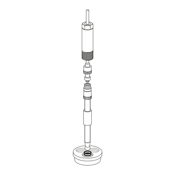
4. Dimensions
For electrode dimensions refer to figure 4 or data in GS 12B06J01-E-E(24)
Fig.4. SM21 dimensions
5. Spare parts
Spare parts are listed in table 3.
Table 3: pH single electrodes spare part list
Part Number
Description
K1520BA
Buffer Solution pH4.01+6.87+9.18(3x0.5L)
K1520BB
Buffer Solution pH 1.68 (3x 0.5L)
K1520BC
Buffer Solution pH 4.01 (3x 0.5L)
K1520BD
Buffer Solution pH 6.87 (3x 0.5L)
K1520BE
Buffer Solution pH 9.18 (3x 0.5L)
K1520JL
ADAPTER Y-CAP - PG13.5 SS
K1523JA
Adapter PG13.5 in F*40 PPO
K1523JB
Adapter PG13.5 to ¾"NPT PPO
K1523JC
Adapter PG13.5-sensors in F*40 SS
K1523JD
Adapter PG13.5 to ¾" NPT SS
K1524AA
O-RING SIL. 10.77x2.62&SLIDE RING (1PC)
K1598AC
Flow fitting (3.1), for SC4A
Advertisement

Related Manuals for YOKOGAWA SM21-AG2


Summary of Contents for YOKOGAWA SM21-AG2
- Page 1 2 or 3. typical warranty period, and the conditions of sale relating to the The electrode fits any Yokogawa cable fitted with the standard nut of During calibration the temperature compensation should be active. The original purchase order should be consulted.
- Page 2 6. Regulatory compliance User Manual Directions for use pH Electrodes IM12B06J01-01EN-P Printed in The Netherlands, 01-2212 Subject to change without notice Copyright©...
Need help?
Do you have a question about the SM21-AG2 and is the answer not in the manual?
Questions and answers