
Related Manuals for Fass HEAVY DUTY Series


Summary of Contents for Fass HEAVY DUTY Series
- Page 1 INSTALLATION MANUAL APPLICATION: HD F16 095G (95gph @ 10psi) HD F16 150G (150gph @ 10psi) Powerstroke 6.4L *bypassing the factory Lift Pump* 2008-2010...
- Page 2 Building extremely “High-Quality” fuel products is our business. We concentrate all of our efforts in this arena. No one else is as specialized as FASS in what we do! This is one of the ingre- dients to insure you are running with the “Highest-Quality” fuel system in the world! We have im- plemented very rigorous testing procedures to provide the “Highest Quality”...
- Page 3 Note: Because of the higher fuel flow these systems have to offer, you may encounter problems with the stock fuel module. FASS can solve this with a Suction Tube Kit. Secure vehicle from ROLLING! Use caution when drilling. Steer clear of any electrical wires , air lines or other damageable components.
- Page 4 4. For best results in accuracy and efficiency (due to training, communication, and our relationship with our dealer network), we recommend an Authorized or ViP FASS Fuel Systems dealer for the installation. They are prepared to install the FASS fuel pumps with the most efficiency. If a situation/problem arises during the installation, they are the most prepared for that situation/problem.
-
Page 5: Installation
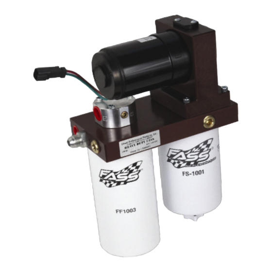
Heavy Duty Series 95 or 150 GPH 10 PSI (Approximately) A fuel pressure gauge is highly recommended to identify fuel filter life and to prevent engine damage! “H” Coolant Heater “E” To Engine ‘T’ Fuel Inlet ‘R’ Fuel Return Electric Heater... - Page 6 Contents MP-9053 *Cable Ties* FB-1009 *WE-1006* BR-2001 WH-1002 FL-1002 x17’...
- Page 7 Mounting Package Contents 10-301 RS-1001 Mounting template PLB-1212 RM-1004 2 Hex Bolt 1/4”-20x1” PLB-1238 PL-1005 3 Hex Bolt 1/4”-20x1.5” Ring Terminal HC-1004 10-300 6 Hex Bolt 3/8” -16x 1 1/4” HC-1001 WA-1001B 6 Locking Nut 3/8” QD-1002 WA-1001A...
- Page 8 Note: The installation of the electrical harness is done first, allowing power to be applied to the pump for lubrication purposes. Note: Use of corrosion preventative spray is recommended. Fuse Neg. a. Using ring terminals, attach red wire of the WH-1002 to the positive bat- tery terminal.
- Page 9 Caution: Make sure there is enough tube on each side of the cut to insert the RM-1004 and to place the hose clamps. a. Mark location on the filler tube that allows you to install RM-1004. Cut tube. b. Position RM-1004 with the junction pipe aiming to outside of bed. Connect rubber and RM-1002 using both HC-1004’s but do not tighten.
- Page 10 WA-1001A & three WA-1001B spacers. Torque to 110 lb./in.² c. Assemble the FASS pump brackets FB-1009 to the BR-2001. Placing the RS-1001 spacer between the brackets, using the 3/8” hex bolts and lock nuts. Hold pump up to the mounting location for rough fitting.
- Page 11 Note - Before Mounting in Position: Route wire harness along frame rail to mounting location. e. Disconnect the factory power plug to the HFCM lift pump. Clean plug and install the WE-1006 connector. Plug female plug of the WH-1002 harness into pump. Turn key on. With pump operating, liberally spray WD-40 (or equivalent) into the water separator nipple.
- Page 12 Note: Hose clamps are not recommended for push lock fittings. They will hold up to 300 psi! a. Route suction line from the tank to port ‘T’ on the FASS system. Cut FL- 1002 to needed length. Insert PL-1005 using oil. Connect to 10-301 in port ‘T’.
- Page 13 Route the fuel line from the ‘E’ port of the FASS to the factory lift pump’s outlet quick disconnect and cut to length. Insert the PLB-1212 into FASS fuel line using oil. Slide the PLB-1212 into the factory quick disconnect until you hear a click.
Need help?
Do you have a question about the HEAVY DUTY Series and is the answer not in the manual?
Questions and answers