Advertisement
Quick Links
TITANIUM SIGNATURE SERIES
INSTALLATION MANUAL
ALL 1/2" FUEL PORTS
Powerstroke 6.7L
*Bypassing the Factory Lift Pump*
Standard Pickup Truck
APPLICATION:
TS-F18-140G
2017-2022
(140GPH @ 65PSI)
LIFETIME
WARRANTY
AVAILABLE
Note: Cab and Chassis
may require modifications
FASS DIESEL FUEL SYSTEMS® / ENGINEERED EXCELLENCE
Advertisement

Subscribe to Our Youtube Channel
Related Manuals for Fass TITANIUM SIGNATURE TS-F18-140G


Summary of Contents for Fass TITANIUM SIGNATURE TS-F18-140G
- Page 1 TITANIUM SIGNATURE SERIES INSTALLATION MANUAL ALL 1/2” FUEL PORTS Powerstroke 6.7L *Bypassing the Factory Lift Pump* Standard Pickup Truck APPLICATION: TS-F18-140G 2017-2022 (140GPH @ 65PSI) LIFETIME WARRANTY AVAILABLE Note: Cab and Chassis may require modifications FASS DIESEL FUEL SYSTEMS® / ENGINEERED EXCELLENCE...
- Page 2 In order to qualify for the lifetime extended warranty, your product registration form and proof of purchase from an authorized dealer must be submitted to FASS Fuel Systems within 30 days of purchase. Failure to comply will void the warranty. We have the right to deny any warranty believed to be false, altered or purchased through an unauthorized or terminated dealer.
- Page 3 -if in doubt check http://fassride.com/locate.php. (If your purchase was made on Amazon.com or Jet.com, the warranty is void. Return the FASS product to the seller and get a refund). 2. It is registered within thirty (30) days of purchase. Other conditions may apply, please see full warranty information.
- Page 4 INSTALLATION OF YOUR NEW TITANIUM FUEL SYSTEM ATTENTION: Be sure to identify the proper FASS System and fuel line configuration. For help, our product finder can be found at www.FASSride.com. Follow the instructions to see fuel line detail. Pay close attention to ALL WARNINGS...
- Page 5 TS-F18-140G: Powerstroke (6.7L) 2017-2022 with stock - 700 horsepower 1. Read all instructions before starting installation of this product! 2. Installing the improper FASS Pump can cause severe engine damage. 3. Secure vehicle from ROLLING! 4. Cab and Chassis may require modifications 5.
- Page 6 (866) 769.3747 WARNING! Always be sure to fill the fuel tank to full after a new FASS installation. Failure to do so can result in excessive sound output, or priming issues!
- Page 7 "H" Coolant Heater Ports Serial Number GUIDE: “T" Fuel Inlet Step 1. Install Electrical Harness Electric Heater Ports Step 2. Prep the FASS "G" Gauge Port Step 3. Mount the FASS Step 4. Fuel Line Supply Step 5. Review Installation...
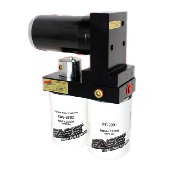
- Page 8 www.fassride.com TITANIUM (866) 769.3747 SIGNATURE SERIES 140 GPH 65 PSI (Ap proximately) Note: Going over 100 PSI WILL void warranty. NOTE: WARRANTY MAY BE VOID IF SILICONE BAND IS REMOVED FROM MOTOR!!
- Page 9 www.fassride.com (866) 769.3747 CONTENTS NOTE: Owner’s Manual available for download on our website, www.FASSride.com FL-1008 LR-1001 FL-1058x5' MP-9077 WH-1006-3 FL-1002x14' OB-1001 PBR-2001 PFB-2002 LRB-1001 RELAY COVER...
- Page 10 www.fassride.com (866) 769.3747 MOUNTING PACKAGE CONTENTS OR-212 46116 TWO (2) ADD-A-CIRCUIT BHF-1005 PL-2003 46177 BHN-1005 TWO (2) RING TWO (2) STF-1001 TERMINAL PLB-1212 QC-4600 A624C56-55-05 TWO (2) 10-305 10-307 10-302 10-300 PL-1058 THREE(3) BOLT 1/2" 1/4"-20x WASHER 1 3/4" TWO (2) TWO (2)HEX BOLT FOUR(4) HEX BOLT 72478...
- Page 11 www.fassride.com (866) 769.3747 MOUNTING PACKAGE CONTENTS RS-2003 RS-2002 RS-2001 TWO (2) THREE (3) HC-1001 FL-1007 SELF TAPPING SCREW CABLE TIES TWO (2) FL-1006 DIELECTRIC GREASE TWO (2) OR-030 OR-017 NOTE: THESE SPARE BASE O-RINGS ARE INCLUDED THREE (3) 1,200°F HEAT SHIELD WITH THE KIT IN THE EVENT OF A PINCHED O-RING DURING ASSEMBLY...
- Page 12 WARNING: (866) 769.3747 The supplied 1,200°F heat shielding must be installed where FASS fuel line routes above the exhaust system. Failure to install heat shielding can result in a possible fire hazard! NOTE: FASS Fuel System will be installed on...
- Page 13 www.fassride.com (866) 769.3747 STEP 1: INSTALL ELECTRICAL HARNESS The installation of the electrical harness is done first, allowing power to be applied to the pump for lubrication purposes later in the installation. NOTE: USE SUPPLIED DIELECTRIC GREASE SPARINGLY ON ALL ELECTRICAL CONNECTIONS! BE SURE TO GREASE RELAY PIGTAIL!
- Page 14 STEP 1: INSTALL ELECTRICAL HARNESS The installation of the electrical harness is done first, allowing power to be applied to the pump for lubrication purposes later in the installation. Install the Relay Cover onto the relay on the FASS harness.
- Page 15 INSTALL ELECTRICAL HARNESS The installation of the electrical harness is done first, allowing power to be applied to the pump for lubrication purposes later in the installation. NOTE: BE SURE TO INSTALL THE SUPPLIED 30 AMP FUSE INTO THE FASS WIRING HARNESS!!
- Page 16 www.fassride.com (866) 769.3747 STEP 1: INSTALL ELECTRICAL HARNESS The installation of the electrical harness is done first, allowing power to be applied to the pump for lubrication purposes later in the installation. A. Crimp the ring terminals to the red and green wires of the WH-1006-3 Wire Harness.
- Page 17 www.fassride.com (866) 769.3747 STEP 1: INSTALL ELECTRICAL HARNESS D. Route the single red wire of WH-1006-3 to the engine bay fuse panel. Remove a fuse (maximum of 10A) that is “hot” when the key is on. Use a test probe to locate the “hot side” of the circuit in the fuse block.
- Page 18 www.fassride.com (866) 769.3747 STEP 2: PREPARE SUCTION & RETURN LINES Some of the photos are of a different application, procedures are the same. NOTE: Before installing fittings make sure to inspect for burs or flare imperfections. When cutting fuel line make sure to blow out line to keep debris from moving forward.
- Page 19 www.fassride.com (866) 769.3747 STEP 2: PREPARE SUCTION & RETURN LINES C. Disconnect factory suction and return lines (refer to diagram at the beginning of step 2). D. With the fuel tank empty of fuel, unbolt the tank straps and remove it from the vehicle. E.
- Page 20 www.fassride.com STEP 2: (866) 769.3747 PREPARE SUCTION & RETURN LINES G. Carefully remove all sections of the OEM convoluted tubing from the fuel tank module using a utility knife. Be sure not to damage the hose barb beneath the convoluted tubing. One of the sections of tubing will have a metal clamp, this can be removed with a small pair of side-cutters.
- Page 21 www.fassride.com STEP 2: (866) 769.3747 PREPARE SUCTION & RETURN LINES H. Remove OEM fuel pump harness from fuel tank module by pressing clips on each side of the connector while pulling in an outward direction. Disconnect the fuel level sending unit electrical connector and remove sending unit from the THIS WILL BE REINSTALLED AT A LATER TIME, DO NOT fuel tank module to prevent damage.
- Page 22 www.fassride.com STEP 2: (866) 769.3747 PREPARE SUCTION & RETURN LINES J. Using a pair of Vice-Grips, lift and retain the fuel tank module springs. Press the 3 locking tabs on the fuel tank module's lower section and remove.
- Page 23 www.fassride.com STEP 2: (866) 769.3747 PREPARE SUCTION & RETURN LINES K. Remove the remaining lower section of the clear convoluted tubing from the fuel tank module with a pair of side-cutters. Mark the location for BHF-1005 and drill with a 7/8" hole saw. BE SURE TO DEBURR THE HOLE!!!!
- Page 24 www.fassride.com STEP 2: (866) 769.3747 PREPARE SUCTION & RETURN LINES M. Install 10-307 into BHF-1005, tighten accordingly. Install BHF-1005 onto fuel tank module with OR-212, apply Loc-Tite onto threads, install BHN-1005 onto fitting. Tighten BHF-1005/BHN-1005 with an appropriate pair of pliers. Be sure to check for proper gasket compression OR-212.
- Page 25 www.fassride.com STEP 2: (866) 769.3747 PREPARE SUCTION & RETURN LINES Install STF-1001 into FL-1007 with HC-1001, tighten hose clamp accordingly. VERY IMPORTANT: Support fuel tank on both ends allowing the natural formation of the tank to take place. Failure to perform this step will hinder precision installation. FUEL TANK SUPPORTS...
- Page 26 www.fassride.com STEP 2: (866) 769.3747 PREPARE SUCTION & RETURN LINES P. Using a tape measure, measure from the bottom of the fuel tank to the top of the o-ring sealing surface where the fuel tank module makes contact and take note of the measurement. Compress fuel tank module to the exact height measurement taken in previous step, measure and mark FL-1007 with 1/4-1/2"...
- Page 27 FL-1006 may need to be trimmed to length. R. Install FL-1006 onto OEM fuel tank module, this is where the FASS will return air/ excess fuel. Place bottom section of FL-1006 into an open area of the fuel tank module that will not obstruct the fuel level float.
- Page 28 Leave factory suction line disconnected as this is now the location for the FASS return, reconnect fill and vent tubes. Install A624C56-55-05 into one end of FL-1002 and connect to factory suction line on fuel tank module, opposing end of hose will later connect to FASS return.
- Page 29 www.fassride.com STEP 2: (866) 769.3747 PREPARE SUCTION & RETURN LINES Reinstall fuel tank into the truck by reversing the steps taken for removal. NOTE: ATTENTION: While installing fittings into Titanium pump Apply side pressure to draw tube of pump IMPROPER PROPER...
- Page 30 When cutting fuel line make sure to blow out line to keep debris from moving forward. Install 10-300 into the "E" port and 10-302 into the "T" port of the FASS, torque to 20 ft./lbs. ***FITTINGS COME EQUIPPED WITH THREAD SEALANT, DO NOT USE THREAD TAPE***...
- Page 31 www.fassride.com (866) 769.3747 STEP 3: MOUNT FUEL SYSTEM C. Install RS-2003 onto OB-1001 by removing the adhesive backing and sticking it onto the OB-1001. Apply firm pressure for 30 seconds to ensure a secure bond. D. Install OB-1001 on to the PASSENGER'S SIDE bed mount with the supplied 14mm nut and washer. E.
- Page 32 F. Position the PBR-2001 to the PFB-2002 pump assembly at the mounting location and check for fit. Once location is established, mark location for mounting in next step. G. Assemble the FASS pump bracket PBR-2001 using the RS-2002 spacer between PFB-2002 and PBR-2001 bracket with 4-3/8 bolts, nuts, and washers. Note: Torque bolts not flange nut.
- Page 33 (866) 769.3747 STEP 3: MOUNT FUEL SYSTEM NOTE: If fuel pressure gauge is pulsating after FASS installation, use snubber valve (Cat Part # 7S-3795) Apply motor oil to gasket located on filters. Attach to system and hand tighten. Extreme Water Separator -...
- Page 34 www.fassride.com STEP 4: (866) 769.3747 INSTALL FUEL LINE Caution: DO NOT use sealant on AN fittings Install the fuel line heat shield on all 3 fuel lines that will be routed over the exhaust system. Be very sure the shielding is perfectly centered above the exhaust! B.
- Page 35 Insert PL-1058 using oil. Connect to 10-302 in port ‘T’. Torque to 18 ft./lbs. D. Route fuel line from the A624C56-55-05 to the ‘R’ port on the FASS system with a gentle bend. Cut and insert PL-2003 using oil. Attach fitting to the ‘R’ port. Do not use any sealant. Torque to 18 ft./lbs.
- Page 36 Caution: DO NOT use sealant on AN fittings E. Insert PL-2003 into remaining fuel line using oil. Attach fuel line to the ‘E’ port of the FASS system. Torque to 18 ft./lbs. Route this line to the engine side of the factory feed line on top of the fuel tank, connect to OEM fuel line with PLB-1212.
- Page 37 Caution: DO NOT use sealant on AN fittings Connect electrical connector on the FASS to the WH-1006-3, turn the key to the "RUN" position and spray WD-40 into the suction side of the FASS. This will allow easier priming of the FASS System.
- Page 38 To assist with priming your FASS pump crack the XWS-3002. Put power to the FASS pump to activate the pump. When the tone of the pump changes you can tighten up the fuel filter. If you need a video of the priming process go to www.FASSride.com.
- Page 39 3. Electrical harness and fuel lines secured and properly tightened? Reconnect the battery. 4. Has the system been primed? a. Turn key to the ignition position, turning on the FASS pump for 15 sec.. b. Crank engine and allow to run for at least 1 minute. 5. Check for leaks.
- Page 40 Disclaimer: To help insure you receive the proper system and customer support at the local level, FASS has a VIP and Authorized Dealer network representing FASS products. This is one reason you must purchase through a dealer to comply with our warranty policies. If you do not, there is no warranty! We recommend you go to www.FASSride.com, click “Find a Dealer”, put in their ZIP code, select the type of dealer, and see if the...
- Page 41 www.fassride.com (866) 769.3747 NOTES:...
Need help?
Do you have a question about the TITANIUM SIGNATURE TS-F18-140G and is the answer not in the manual?
Questions and answers