Table of Contents
Advertisement
Quick Links
Ginlong Technologies Co., Ltd.
No. 57 JintongRoad, Binhai Industrial Park, Xiangshan, Ningbo,
Zhejiang, 315712, P.R.China.
Tel: +86 (0)574 6578 1806
Fax: +86 (0)574 6578 1606
Please adhere to the actual products in case of any discrepancies in this user manual.
If you encounter any problem on the inverter, please find out the inverter S/N
and contact us, we will try to respond to your question ASAP.
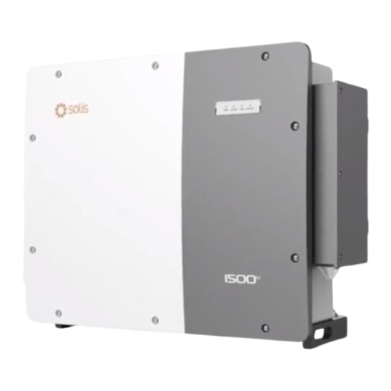
Solis Three Phase Inverter
Installation and Operation Manual
(300-350)K
Ginlong Technologies Co., Ltd.
Ver 1.0
Advertisement
Table of Contents

Subscribe to Our Youtube Channel
Related Manuals for SOLIS S6-GU350K-EHV


Summary of Contents for SOLIS S6-GU350K-EHV
- Page 1 Solis Three Phase Inverter Installation and Operation Manual (300-350)K Ver 1.0 Ginlong Technologies Co., Ltd. No. 57 JintongRoad, Binhai Industrial Park, Xiangshan, Ningbo, Zhejiang, 315712, P.R.China. Tel: +86 (0)574 6578 1806 Fax: +86 (0)574 6578 1606 Please adhere to the actual products in case of any discrepancies in this user manual.
-
Page 2: Table Of Contents
Contents 1. Introduction ………………………………………………………………………………………………………………………………………… 1.1 Product Description ……………………………………………………………………………………………………… 1.2 Unpacking and storage ……………………………………………………………………………………………… 1.2.1 Storage ……………………………………………………………………………………………………………… 2. Safety instructions ……………………………………………………………………………………………………………………… 2.1 Safety symbols ……………………………………………………………………………………………………………… 2.2 General safety instructions ……………………………………………………………………………………… 2.3 Notice for use ………………………………………………………………………………………………………………… 2.4 Notice for Disposal ……………………………………………………………………………………………………… 3. Installation …………………………………………………………………………………………………………………………………………... -
Page 3: Introduction
1.1 Product Description 1.2 Unpacking and storage Solis Three phase Inverters covert DC power from the photovoltaic(PV) array The inverter ships with all accessories in one carton. into alternating current(AC) power that can satisfy local loads as well as feed the power When unpacking, please verify all the parts listed below are included: distribution grid. -
Page 4: Storage
1. Introduction 2. Safety Instructions 1.2.1 Storage Improper use may result in electric shock hazards or burns. This product manual contains important instructions that are required to be followed during installation and maintenance. If the inverter is not installed immediately, storage instructions and environmental conditions are below: Please read these instructions carefully before use and keep them in an easily locatable place ●... -
Page 5: Notice For Use
2. Safety Instructions 3. Installation 3.1 Environmental considerations 3.1.1 Select a location for the inverter CAUTION When selecting a location for the inverter, consider the following: Risk of electric shock from energy stored in the inverter's capacitors. Do not remove cover until 20 minutes after disconnecting all sources WARNING: Risk of fire of supply have passed, and this can only be done by a service technician. -
Page 6: Other Environmental Considerations
3. Installation 3. Installation 3.1.2 Other environmental considerations When multiple inverters are installed and the space is sufficient, a zigzag installation is 3.1.2.1 Consult technical data recommended. Font type, back-to-back installation is not recommended. Consult the specifications section (section 10) for additional environmental conditions Do not install it stacked up and down. -
Page 7: Mounting The Inverter
3. Installation 3. Installation 3.3 Mounting the Inverter The inverter can be mounted to the wall or metal array racking. The mounting holes should be consistent with the size of the bracket or the dimensions shown in Figure 3.7. unit:mm Figure 3.5 Inverter handles Figure 3.7 Inverter wall mounting WARNING... -
Page 8: Electrical Connections
3. Installation 3. Installation 3.4.1 Grounding Use screws in the packaging to fix the inverter to the mount bracket To effectively protect the inverter, two grounding methods must be performed. Connect the AC grounding cable (Please refer to section 3.4.3) Connect the external grounding terminal. -
Page 9: Connect Pv Side Of Inverter
3. Installation 3. Installation 3.4.2 Connect PV side of inverter 4) Insert the stripped wire into the OT terminal crimping area and use the hydraulic WARNING clamp to crimp the terminal to the wire. Before connecting the inverter, make sure the PV array open circuit voltage is within the limit of the inverter. -
Page 10: Connect Grid Side Of Inverter
3. Installation 3. Installation 3.4.2.1 DC connection high voltage danger notice 5. Measure PV voltage of DC input with multimeter, verify DC input cable polarity (see figure 3.17), and ensure each string voltage is in range of inverter operation. CAUTION Connect DC connector with inverter until hearing a slight clicking sound indicating RISK OF ELECTRIC SHOCK successful connection. - Page 11 S6-GU333K-EHV-M16 240.3 Cable ampacity of ground wire should be more than half of cable ampacity of live wire. S6-GU350K-EHV-M12 252.6 S6-GU350K-EHV-M16 252.6 1) Strip the end of AC cable insulating jacket about 300mm then strip the end of each wire.
- Page 12 When multiple inverters are connected to the grid in parallel, ensure that the maximum number spring washer of inverters connected in parallel to a single winding of the box-type substation is 15. Otherwise, please contact Solis for technical scheme. L1 L2 L3 3.4.3.4 MV Transformer The MV transformer used together with the inverter should meet the following requirements: M6 5-7 N.m...
-
Page 13: Rs485 And Plc Communication Connection
4. Comm. & Monitoring 4. Comm. & Monitoring There are 5 communication terminals on the inverters. PLC is available for multiple inverter monitoring. COM1 is a 4-pin connector reserved for WiFi/Cellular datalogger. 2*RS485 ports are for RS485 communication between inverters. DRM port is for DRM connection. -
Page 14: Logic Interface Connection
1. Insert the network cable into the communication connection terminal of RJ45. continuously lit. 4). Solis inverters are powered from the DC side. When the inverter detects DC power that is within start-up and operating ranges, the inverter will turn on. After turn- on, the inverter will check internal parameters, sense and monitor AC voltage, hertz rate and the stability of the supply grid. -
Page 15: Normal Operation
6. Normal operation 6. Normal operation 6.1 APP Download Users need to download the APP before installing it for the first time. Step 3: Login account. There are three ways to download and install the latest APP: If you are the installer, please select the account type as Installer. If you are the plant owner, 1. -
Page 16: Home Page
6. Normal operation 6. Normal operation 6.4 Info Page The APP interface contains 4 sections: Info page displays the general information of the inverter such as inverter serial number, firmware version, grid code, etc. 1. Home 2. Info 3. Alarm 4. -
Page 17: Maintenance
Never use any solvents, abrasives or corrosive materials to clean the inverter. 7.1 Anti-PID Function Solis Three phase Inverters integrates optional Anti-PID module and it can recover the PID effect during night thus protect the PV system from degradation. Inverter Figure 7.1... -
Page 18: Fan Maintenance
7. Maintenance 8. Troubleshooting The inverter is designed in accordance with the most important international grid-tied NOTE: standards and safety and electromagnetic compatibility requirements. Before delivering to If you need to maintain the inverter at night, please turn off the AC switch first, the customer, the inverter has been subjected to several tests to ensure its optimal operation then turn off the DC switch, and wait 20 minutes before you do other operations. -
Page 19: Troubleshooting
1. Serial number of Solis Three Phase Inverter; if there are strings reversely connected wait for One of the DC string is 2. The distributor/dealer of Solis Three Phase Inverter (if available); Reve-DC the night when the solar irradiance is low and the reversely connected PV string current down below 0.5A. -
Page 20: Specifications
9. Specifications 9. Specifications Model S6-GU300K-EHV-M12 Model S6-GU300K-EHV-M16 Max. DC input voltage (Volts) 1500 Max. DC input voltage (Volts) 1500 Rated DC voltage (Volts) Rated DC voltage (Volts) 1080 1080 Start-up voltage (Volts) Start-up voltage (Volts) MPPT voltage range (Volts) MPPT voltage range (Volts) 480...1500 480...1500... - Page 21 9. Specifications 9. Specifications Model S6-GU333K-EHV-M12 Model S6-GU333K-EHV-M16 Max. DC input voltage (Volts) 1500 Max. DC input voltage (Volts) 1500 Rated DC voltage (Volts) Rated DC voltage (Volts) 1080 1080 Start-up voltage (Volts) Start-up voltage (Volts) MPPT voltage range (Volts) MPPT voltage range (Volts) 480...1500 480...1500...
- Page 22 9. Specifications 9. Specifications Model S6-GU350K-EHV-M12 Model S6-GU350K-EHV-M16 Max. DC input voltage (Volts) 1500 Max. DC input voltage (Volts) 1500 Rated DC voltage (Volts) Rated DC voltage (Volts) 1080 1080 Start-up voltage (Volts) Start-up voltage (Volts) MPPT voltage range (Volts) MPPT voltage range (Volts) 480...1500...
Need help?
Do you have a question about the S6-GU350K-EHV and is the answer not in the manual?
Questions and answers