
Subscribe to Our Youtube Channel
Related Manuals for SEELEY INTERNATIONAL Dominator KGHV200A1S


Summary of Contents for SEELEY INTERNATIONAL Dominator KGHV200A1S
- Page 1 INSTALLATION MANUAL DUCTED INVERTER AIR CONDITIONER Dominator Series KGHV200A1S / KCHV160D1B KGHV200A1S / KCHV160D1B...
- Page 2 CHECKING RECEIVED PRODUCT Upon receiving the appliance, please inspect for damage. Claims for damage should be reported immediately with the transportation company. Check the model number of the appliance and ensure it matches the order. In the event an incorrect appliance or a damaged appliance is delivered, it must be returned to the supplier and must NOT be installed.
-
Page 3: Table Of Contents
FAN CURVE MATRIX DETERMINATION OF CORRECT REFRIGERANT CHARGE ERROR CODES BRAEMAR REFRIGERATED AIR CONDITIONING - COMMISSIONING SHEET COMMISSIONING CHECKLIST SERVICING REQUIREMENTS WITH FLAMMABLE REFRIGERANTS REMOVAL AND DISPOSAL TECHNICAL SPECIFICATIONS WIRING SCHEMATICS QUICK REFERENCE GUIDE NOTES SEELEY INTERNATIONAL - INSTALLATION MANUAL |... -
Page 4: Safety Warnings
SAFETY WARNINGS Before installing the appliance, Appliance filled with flammable gas R32. read the installation manual first. Before repairing the appliance, Before using the appliance, read the read the service manual first. owner’s manual first. WARNING Do not use means to accelerate the defrosting process or to clean, other than those recommended by the manufacturer. The appliance shall be stored in a room without continuously operating ignition sources (for example: open flames, an operating gas appliance or an operating electric heater. - Page 5 • Discharge capacitors in a way that won’t cause any spark. • Reclaim the refrigerant. e) Disposal • Ensure sufficient ventilation at the working place. • Reclaim the refrigerant. • Evacuate the refrigerant circuit. SEELEY INTERNATIONAL - INSTALLATION MANUAL |...
-
Page 6: Before Installation
• Servicing shall be performed only as recommended by Seeley International • For ducted systems, the supply and return air shall be directly ducted to the conditioned space. Open areas such as false ceilings shall not be used as a return air duct. - Page 7 Auxiliary devices which may be a potential ignition source shall not be installed in the duct work. Examples of such potential ignition sources are hot surfaces with a temperature exceeding 700°C and electric switching devices. Only auxiliary devices approved by Seeley International or declared suitable with the refrigerant shall be installed in connecting ductwork. Cabling Check that the cabling will not be subject to wear, corrosion, excessive pressure, vibration, sharp edges or any other adverse environmental effects.
- Page 8 Before using the recovery machine, check that it is in satisfactory working order, has been properly maintained and that any associated electrical components are sealed to prevent ignition in the event of a refrigerant release. Consult Seeley International if in doubt.
-
Page 9: Typical Installation/Diagram Of Key Components
Button 2 WIFI Wired Remote Wired Remote RS485 Module Controller 1 Controller 2 Extension 1. Power Cable 2. Zone Control Kit 3. Binding Tape 4. Liquid Pipe 5. Gas Pipe 6. Drain Pipe Fig 01 SEELEY INTERNATIONAL - INSTALLATION MANUAL |... -
Page 10: Installation
INSTALLATION COMPONENTS Parts listed below are supplied and should be used as required. Indoor Unit Accessories Name Appearance Q’ty Usage Power Zone Damper Zone control Kit Refer to separate manual for controller. Antenna Button 1 Button 2 WIFI Wired Remote Wired Remote Module RS485... -
Page 11: Necessary Tools For Installation
Hole core drill • Torque Wrench • Knife • Open-end spanner set INDOOR UNIT DIMENSIONS 1159 1180 DRAIN CONNECTION SIDE FRONT Fig 02 Return Air Supply Air Optional Return Air Optional Supply Air Optional Supply Air SEELEY INTERNATIONAL - INSTALLATION MANUAL |... -
Page 12: Indoor Unit Installation
INSTALLATION cont. INDOOR UNIT INSTALLATION MAKE SURE THE COOLING COIL IS INSTALLED WITH AIRFLOW IN THE DIRECTION AS SHOWN ON THE DECAL ON THE UNIT. The indoor unit can be mounted on a suitable base. Ensure that the base is level and that the drains are free to be piped correctly with enough height to allow for condensate trap and fall to waste. -
Page 13: Flexible Ductwork Connections
Drain may run on grade from the pump outlet, or rise a maximum of 1m above the underside of the unit and then run on grade to the discharge point. Do not use silicon for drain installation. 1. Metal Clamp Drain trap with tee for clean out 2. Drain hose 3. Insulation Fig. 04 SEELEY INTERNATIONAL - INSTALLATION MANUAL |... -
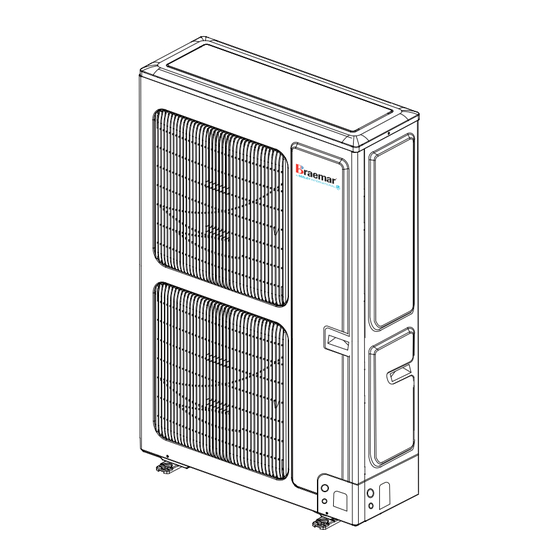
Page 14: Outdoor Unit Installation
OUTDOOR UNIT INSTALLATION Fig. 05 Dimension (mm) Width Depth Height Bolt Holes MODEL KCHV160D1B 1430 Table 03 KGHV Series Inverter Ducted... -
Page 15: Outdoor Unit Clearances
≥300 ≥1000 ≥1000 C, E ≥2000 D, E ≥2000 ≥1000 B, D ≥300 ≥2500 B, D, E ≥300 ≥2500 ≥1000 Fig. 07 Table 05 When outdoor units are installed one above another Fig. 08 SEELEY INTERNATIONAL - INSTALLATION MANUAL |... -
Page 16: Condensate Drainage
OUTDOOR UNIT INSTALLATION - cont. Location considerations should: • Most importantly, do not install the Outdoor unit where there is a possibility it will cause a noise complaint from neighbours. Be mindful of the environment. Installers must comply with noise regulations and ensure air discharge and operating sound levels conform to local requirements. -
Page 17: Refrigerant Pipe-Work
Install an oil return bend every 6m DIMENSIONS OF OIL RETURN BEND mm(inch) (mm) (mm) 9.53( ) ≥20 ≤150 15.88( ) ≥33 ≤150 Table 06 Fig. 12 SEELEY INTERNATIONAL - INSTALLATION MANUAL |... -
Page 18: Brazing
REFRIGERANT PIPE WORK - cont. BRAZING If brazing of pipe-work is required, dry nitrogen must be used to purge the pipe-work during welding. If any brazing is performed in close proximity of service valves or the Microchannel indoor coil, a wet cloth must be used to ensure these sensitive parts are not damaged. -
Page 19: Connection Between Indoor Unit And Outdoor Unit
Outdoor unit is fitted with an ‘11’ jumper plug, replace this with the “09” Jumper plug supplied with the install kit when connecting to a Dominator Series KGHV200A1S appliance. Fig. 15 SEELEY INTERNATIONAL - INSTALLATION MANUAL |... -
Page 20: Sealing The Knock-Out Hole
REFRIGERANT PIPE WORK - cont. SEALING THE KNOCK-OUT HOLE For 16kW unit when connecting the pipes and power cable or communication wire during installation, use the sealing pad and rubber ring after threading the connection pipe and power cable or communication wire to the knock-out hole, and wrap the tail of sealing pad with the pipe when wrapping the tape. -
Page 21: Leak Detection Methods
UV tape or a suitable pipe cover to prevent the pipe insulation and electrical connections from being damaged. NOTE: Condensate is to be drained off to a catchment point in Trap accordance with local, state and national regulations. Fig. 19 SEELEY INTERNATIONAL - INSTALLATION MANUAL |... -
Page 22: Electrical Wiring
ELECTRICAL WIRING MAINS & CONTROL WIRING WARNING! Only licensed trades persons must carry out all the wiring work. Check AS/NZS WIRING RULES for PROTECTION sizing and cable sizes . Always refer to the relevant wiring standard for the electrical installation, and ensure the appliance is installed in accordance with local, state and national wiring regulations. -
Page 23: Wiring Precautions
4. Communication cable 2×0.75mm 5. Connection wires of DRED module Note: Above power cable sizes are a recommended minimum, upsizing of the power cable may be required based upon the installed location relative to the electrical switchboard. SEELEY INTERNATIONAL - INSTALLATION MANUAL |... -
Page 24: Dred Connection
ELECTRICAL WIRING - cont. DRED CONNECTION CAUTION: For the connection wire and power cable of DRED module, it’s suggested to use a cable that is suitable for outdoor use. Otherwise install the power cable and connection wire in conduit that protects against rain and UV rays. The DRED module should be installed indoors or inside an enclosed space protected from rain and UV light. -
Page 25: Zone Control Kit Le60-13/Gh-Kit-B
Provided in box Wired wall control XE70-13/E Provided in box Transfomer Provided in box 450002060017 Smart Phone Supplied by end user OPTIONAL Wifi Module ME31-00/C13 Optional additional part Table 13 Note: WiFi connection not supplied SEELEY INTERNATIONAL - INSTALLATION MANUAL |... -
Page 26: Start Up And Commissioning
START UP AND COMMISSIONING • Ensure the electrical wiring has been completed, connected and switched on at Isolator. • Switch the Unit(s) on in cooling mode one at a time, ensuring that the system has been correctly wired and piped up on a multi system. -
Page 27: Fan Curve Matrix
At maximum fan power, high airflows at high ESP are limited. The reported airflows above 100Pa for 900 L/s and above 250Pa for 800 L/s are the highest achievable under these conditions. At 400 L/s the testing apparatus was unable to provide enough back pressure to determine airflows at ESP above 200Pa. SEELEY INTERNATIONAL - INSTALLATION MANUAL |... -
Page 28: Determination Of Correct Refrigerant Charge
DETERMINATION OF CORRECT REFRIGERANT CHARGE The Outdoor unit comes pre-charged with Refrigerant R32, refer to Table 15 to determine if refrigerant needs to be added or removed. Refer to point 7b on page 36 for guidance on adding/removing refrigerant charge. Pre-charge Add/Remove Refrigerant (g/m) MODEL... -
Page 29: Error Codes
Overload IPM protection DC fan error Driver out-of-step protection PFC protection Startup failure Compressor phase-sequence protection Power protection IDU and ODU unmatched 4-way Valve switch over error Driver reset protection Over-current protection Table 17 SEELEY INTERNATIONAL - INSTALLATION MANUAL |... -
Page 30: Braemar Refrigerated Air Conditioning - Commissioning Sheet
BRAEMAR REFRIGERATED AIR CONDITIONING - COMMISSIONING SHEET Please complete at time of commissioning on site: CUSTOMER: Name: ....................Date: ............Street: ....................Dealer: ............Suburb: ....................Installer: ............. State: ....................Post Code: ......Phone (H): ........... (W): ......Dominator Series Model: .............. -
Page 31: Commissioning Checklist
Asked the home owner/user if they have any questions about how to use or maintain the Braemar Refrigerated Air Conditioning unit. Customer Signature ..............Date ..............Installer Signature ............... Date ..............System design notes: Indoor details: please provide room details Cooling mode: Heating mode: ................................SEELEY INTERNATIONAL - INSTALLATION MANUAL |... -
Page 32: Servicing Requirements With Flammable Refrigerants
SERVICING REQUIREMENTS WITH FLAMMABLE REFRIGERANTS CHECKS TO THE AREA Prior to beginning work on systems containing flammable refrigerants, safety checks are necessary to ensure that the risk of ignition is minimised. Work shall be undertaken under a controlled procedure so as to minimise the risk of a flammable gas or vapour being present while the work is being performed. -
Page 33: Removal And Disposal
For complete warranty terms and conditions, refer to separate Warranty Booklet and/or www.braemar.net.au Warranty conditions are subject to property access and industry Safety Standards. Seeley International strives for continuous product improvements, therefore specifications are subject to change without notice. Unit colour may vary slightly from that depicted in this booklet. -
Page 34: Technical Specifications
TECHNICAL SPECIFICATIONS Outdoor KCHV160D1B Model Indoor KGHV200A1S Rated Heating Capacity 20.00 Heating Capacity Range (Min~Max) 5.40 ~ 24.75 Heating Capacity at 2°C 15.00 Rated Cooling Capacity 12.20 Cooling Capacity Range 2.30 ~ 16.50 HSPF Residential (Hot / Average / Cold) 5.495 / 4.503 / 3.803 TCSPF Residential (Hot / Average / Cold) 4.262 / 4.095 / 4.224... -
Page 35: Wiring Schematics
WIRING SCHEMATICS 646237 671447 Tube Sensor R/A Sensor FAN / PUMP WALL OUTDOOR CONTROL UNIT H1 H2 MAINS IN WALL CONTROL PUMP WATER MOTOR LEVEL OUTDOOR SENSOR UNIT Field Wiring SEELEY INTERNATIONAL - INSTALLATION MANUAL |... -
Page 36: Quick Reference Guide
QUICK REFERENCE GUIDE DESIGN: 1. Duct design (refer page 12 for more detail) a. Return air 4m/s maximum velocity, due to high capacity of the EC backward curved fan, flexible duct too small (velocities too high) can implode. b. Confirm the required amount of air can be carried through to each room via the existing ducting, below calculations may be useful when deciding if duct can carry the required amount of heating to each room. - Page 37 Temp on/off control parameters: In cooling mode: cooling starts at set point and stops at set point minus 2°C, ii. In heating mode: heating starts at set point and stops at set point plus 2°C. SEELEY INTERNATIONAL - INSTALLATION MANUAL |...
-
Page 38: Notes
NOTES KGHV Series Inverter Ducted... - Page 39 NOTES SEELEY INTERNATIONAL - INSTALLATION MANUAL |...
- Page 40 Online Support Portal (AUS/NZ) Scan or Click QR Code It is the policy of Seeley International to introduce continuous product improvement. Accordingly, specifications are subject to change without notice. Please consult with your dealer to confirm the specifications of the model selected.
Need help?
Do you have a question about the Dominator KGHV200A1S and is the answer not in the manual?
Questions and answers