• Introduction These mounting instructions describe the steps for mounting supported Cisco Aironet series access points in several configurations, including on a suspended ceiling, on a hard ceiling or wall, on an electrical or network box, and above a suspended ceiling.
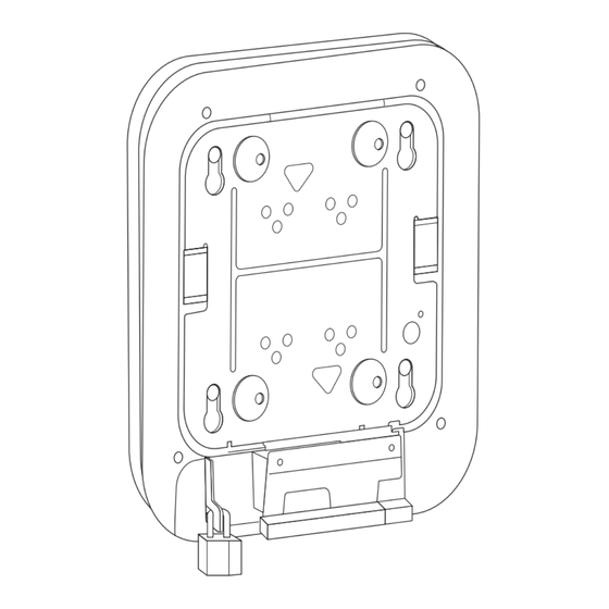
Page 2
Mounting Hardware Mounting Brackets Two mounting brackets are available: The low-profile bracket (AIR-AP-BRACKET-1), which provides a tight fit between the access point • and the ceiling but does not accommodate network/electrical box or wall mounting. Figure 1 shows the low-profile bracket installed on an access point.
Page 3
Mounting Hardware Figure 2 Universal Bracket Installed on an Access Point Ceiling Grid Clips You use a ceiling grid clip to mount an access point on a suspended ceiling. The ceiling grid clip that you need depends on the ceiling tiles on your ceiling. There are two types of ceiling grid clips: Ceiling Grid Clip, Recessed (AIR-AP-T-RAIL-R)—If your ceiling tiles hang below the ceiling grid, •...
Page 4
Mounting Hardware Locking screws T-rail width detents (A, B, or C) Bracket screw holes Additional Adapters for Channel and Beam Ceiling Rails The most common type of ceiling rail (the supports for the ceiling tiles) is the T-rail. You can attach a ceiling grid clip directly to a T-rail ceiling rail.
Mounting an Access Point Below a Suspended Ceiling Mounting an Access Point Below a Suspended Ceiling Follow these steps to mount the access point below a standard or recessed suspended ceiling. Figure 6 shows an access point mounted on a T-rail ceiling rail using a ceiling grid clip. Figure 6 Suspended Ceiling Mounting Details Access point mounting keyhole...
Mounting an Access Point on a Hard Ceiling or a Wall (Optional) Use the ground screw to ground the access point to a suitable building ground. See the Step 9 “Grounding an Access Point” section on page 10 for general grounding instructions. Connect the Ethernet and power cables to the access point.
Page 7
Use a #29 drill (0.1360-in. [3.4772 mm]) bit to drill a pilot hole at the mounting hole locations you Step 2 marked. The pilot hole size varies according to the material and thickness you are fastening. Cisco Note recommends that you test the material to determine the ideal hole size for your mounting application.
Mounting an Access Point to a Network or Electrical Box Pull approximately 9 inches of cable through the hole. Route the Ethernet and power cables through the Step 4 bracket before you attach the bracket to the ceiling or wall. Route the cables through the main cable access hole and then through the smaller access hole as shown in Figure Figure 8...
Step 7 Mounting an Access Point Above a Suspended Ceiling Using third-party accessories (not offered by Cisco) you can mount an access point above a suspended ceiling. The universal mounting bracket (AIR-AP-BRACKET-2) supports a T-bar box hanger such as the Erico Caddy 512A or the Cooper B-Line BA50a.
Step 8 Grounding an Access Point Grounding is not always required for indoor installations because Cisco Aironet access points are classified as low-voltage devices and do not contain internal power supplies. We recommend that you check your local and national electrical codes to see if grounding is a requirement.
Page 11
Grounding an Access Point Figure 10 Installing the O-Ring Lug to the Grounding Post Use a Phillips screwdriver to tighten the ground screw. Step 7 Access Point Mounting Instructions OL-166451-01...
Securing an Access Point Securing an Access Point There are two ways to secure your access point: Attach it to an immovable object with a security cable. • Lock it to the mounting plate with a padlock. • Using a Security Cable You can secure the access point by installing a standard security cable (such as the Kensington Notebook MicroSaver, model number 64068) into the access point security cable slot as shown in Figure...
Page 13
Securing an Access Point Securing the Access Point to the Mounting Plate Use the security hasp on the adapter cable access cover and a padlock (that you provide) to secure your access point to the mounting plate. Compatible padlocks are Master Lock models 120T or 121T. The cable access cover on the mounting bracket covers the cable bay area (including the power port, Ethernet port, console port, and the mode button) to prevent the installation or removal of the cables or the activation of the mode button.
Page 14
Cisco currently supports RSS Version 2.0. Cisco and the Cisco Logo are trademarks of Cisco Systems, Inc. and/or its affiliates in the U.S. and other countries. A listing of Cisco's trademarks can be found at www.cisco.com/go/trademarks. Third party trademarks mentioned are the property of their respective owners. The use of the word partner does not imply a partnership relationship between Cisco and any other company.
Need help?
Do you have a question about the AIR-AP-BRACKET-1 and is the answer not in the manual?
Questions and answers