
Related Manuals for ASROCK 775VM800


Summary of Contents for ASROCK 775VM800
- Page 1 775VM800 User Manual Version 1.1 Published May 2005 Copyright©2005 ASRock INC. All rights reserved. 1 1 1 1 1...
- Page 2 (including damages for loss of profits, loss of business, loss of data, interruption of business and the like), even if ASRock has been advised of the possibility of such damages arising from any defect or error in the manual or product.
-
Page 3: Table Of Contents
2.10 Hot Plug and Hot Swap Functions for SATA HDDs ..20 2.11 Installing Windows 2000 / XP / XP 64-bit With RAID Functions ..............21 2.12 Installing Windows 98 / ME / 2000 / XP / XP 64-bit Without RAID Functions ..........23 3. BIOS S 3. - Page 4 4.2 Support CD Information ..........39 4.2.1 Running Support CD ..........39 4.2.2 Drivers Menu ............39 4.2.3 Utilities Menu ............39 4.2.4 “LGA 775 CPU Installation Live Demo” Program..39 4.2.5 Contact Information ..........39 4 4 4 4 4...
-
Page 5: Introduction 1. Introduction
ASRock’s commitment to quality and endurance. In this manual, chapter 1 and 2 contain introduction of the motherboard and step-by- step guide to the hardware installation. Chapter 3 and 4 contain the configuration guide to BIOS setup and information of the Support CD. -
Page 6: Specifications
1.2 Specifications 1.2 Specifications 1.2 Specifications 1.2 Specifications 1.2 Specifications Platform: Micro ATX Form Factor: 9.6-in x 8.2-in, 24.4 cm x 20.8 cm CPU: 775-Pin Socket supporting Intel ® 840EE / Pentium ® D / Pentium ® 4 / Celeron ®... - Page 7 To improve heat dissipation, remember to spray thermal grease between the CPU and the heatsink when you install the PC system. Do NOT use a 3.3V AGP card on the AGP slot of this motherboard! It may cause permanent damage! Power Management for USB 2.0 works fine under Microsoft...
-
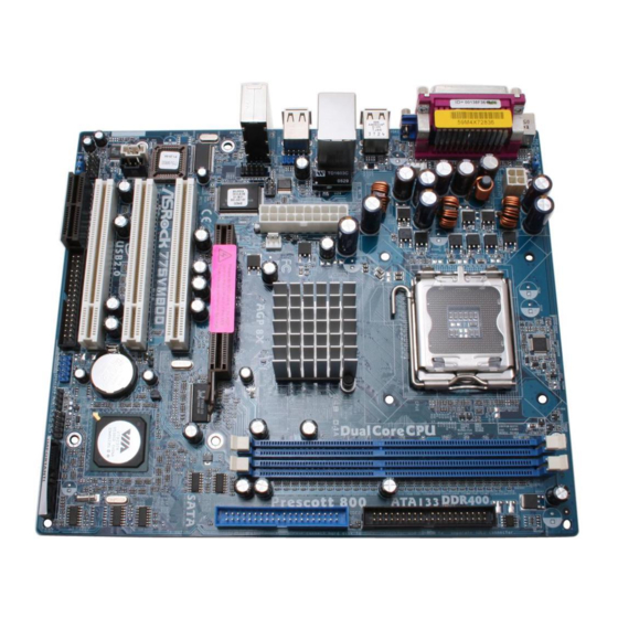
Page 8: Motherboard Layout
775-Pin CPU Socket JR1 / JL1 Jumpers North Bridge Controller Front Panel Audio Header (AUDIO1) 2 x 184-pin DDR DIMM Slots (DDR1, DDR2; Blue) Internal Audio Connector: CD1 (Black) Secondary IDE Connector (IDE2, Black) Internal Audio Connector: AUX1 (White) Primary IDE Connector (IDE1, Blue) 3 x PCI Slots (PCI1- 3) AGP Slot (1.5V_AGP1) -
Page 9: Asrock I/O Plus
Parallel Port USB 2.0 Ports (USB01) RJ-45 Port USB 2.0 Ports (USB23) Line In (Light Blue) VGA Port Line Out (Lime) PS/2 Keyboard Port (Purple) Microphone (Pink) PS/2 Mouse Port (Green) Shared USB 2.0 Ports (USB45) 9 9 9 9 9... -
Page 10: Installation
Chapter 2 Installation Chapter 2 Installation 775VM800 is a Micro ATX form factor (9.6" x 8.2", 24.4 x 20.8 cm) motherboard. Before you install the motherboard, study the configuration of your chassis to ensure that the motherboard fits into it. -
Page 11: Cpu Installation
Before you insert the 775-LAND CPU into the socket, please check if the CPU surface is unclean or if there is any bent pin on the socket. Do not force to insert the CPU into the socket if above situation is found. - Page 12 PnP cap to assist in removal. It is recommended to use the cap tab to handle and avoid kicking off the PnP cap. Step 4. Close the socket: Step 4-1.
-
Page 13: Installation Of Cpu Fan And Heatsink
CPU and the heatsink to improve heat dissipation. Ensure that the CPU and the heatsink are securely fastened and in good contact with each other. Then connect the CPU fan to the CPU_FAN connector (CPU_FAN1, see page 8, No. -
Page 14: Installation Of Memory Modules (Dimm)
DIMMs or the system components. Step 1. Unlock a DIMM slot by pressing the retaining clips outward. Step 2. Align a DIMM on the slot such that the notch on the DIMM matches the break on the slot. notch break... -
Page 15: Expansion Slots (Pci, Amr And Agp Slots)
AMR slot: The AMR slot is used to insert an ASRock MR card with v.92 Modem functionality. AGP slot: The AGP slot is used to install a graphics card. The ASRock AGP slot has a special design of clasp that can securely fasten the inserted graphics card. -
Page 16: Jumpers Setup
Note: To select +5VSB, it requires 2 Amp and higher standby current provided by power supply. (see p.8, No. 20) (see p.8, No. 20) Note: If the jumpers JL1 and JR1 are short, both the front panel and the rear panel audio connectors can work. Clear CMOS (CLRCMOS1, 2-pin jumper) 2-pin jumper (see p.8, No. -
Page 17: Onboard Headers And Connectors
FLOPPY1 Pin1 (see p.8, No. 18) the red-striped side to Pin1 Note: Make sure the red-striped side of the cable is plugged into Pin1 side of the connector. Primary IDE Connector (Blue) Secondary IDE Connector (Black) (39-pin IDE1, see p.8, No. 9) (39-pin IDE2, see p.8, No. - Page 18 ASRock I/O Plus provides you 6 ready-to-use USB 2.0 ports on (9-pin USB67) DUMMY the rear panel. If the rear USB (see p.8, No. 17) ports are not sufficient, this USB 2.0 header is available to USB_PWR support 2 extra USB 2.0 ports.
- Page 19 Failing to do so will cause the failure to power up. Please install the heatsink and the CPU fan before installing ATX 12V connector; otherwise, it may cause permanent damage! Serial port connector...
-
Page 20: Serial Ata (Sata) Hard Disks Installation
STEP 3: Connect one end of the SATA data cable to the motherboard’s SATA connector. STEP 4: Connect the other end of the SATA data cable to the SATA hard disk. 2.10 Hot Plug and Hot Swap F 2.10 Hot Plug and Hot Swap F 2.10 Hot Plug and Hot Swap Functions for SA... -
Page 21: Functions
Windows XP 64-bit With RAID Functions Windows XP 64-bit With RAID Functions If you want to install Windows 2000 / Windows XP / Windows XP-64bit OS on your system with RAID functions, please follow the below steps. STEP 1: Make a SATA Driver Diskette. - Page 22 Support CD, “Guide to SATA Hard Disks Installation and RAID Configuration”, which is located in the folder at the following path: .. \ SATA RAID BIOS and the document in the support CD, “Guide to VIA RAID Tool”, which is located in the folder at the following path: ..
-
Page 23: Installing Windows 98 / Me / 2000 / Xp / Xp 64-Bit
Without RAID Functions If you want to install Windows 98 / ME / 2000 / XP / XP 64-bit on your SATA HDDs without RAID functions or you want to install Windows 98 / ME / 2000 / XP / XP 64-bit on your IDE HDDs instead of SATA HDDs, please follow the below steps. -
Page 24: Etup Utility
Power-On-Self-Test (POST) to enter the BIOS SETUP UTILITY, otherwise, POST will continue with its test routines. If you wish to enter the BIOS SETUP UTILITY after POST, restart the system by pressing <Ctl> + <Alt> + <Delete>, or by pressing the reset button on the system chassis. -
Page 25: Navigation Keys
To jump to the Exit Screen or exit the current screen 3.2 Main Screen Main Screen Main Screen Main Screen Main Screen When you enter the BIOS SETUP UTILITY, the Main screen will appear and display the system overview BIOS SETUP UTILITY Advanced H/W Monitor Boot... -
Page 26: Cpu Configuration
Select [Auto] for the spread spectrum feature. Ratio Status This is a read-only item, which displays whether the ratio status of this motherboard is “Locked” or “Unlocked”. If it shows “Unlocked”, you will find an item Ratio CMOS Setting appears to allow you changing the ratio... -
Page 27: Chipset Configuration
Setting will be hidden. If you use the ratio value to time the CPU frequency, it will be equal to the core speed of the installed processor. Ratio Actual Value This is a read-only item, which displays the ratio actual value of this motherboard. - Page 28 The default value of this feature is set to [Auto]. If you install an 8X-AGP card on this motherboard, you may select [Auto], [8X] or [4X] as the AGP mode. If the installed AGP card is a 4X-AGP card, then you may set the AGP mode as [Auto], [4X], [2X], or [1X].
-
Page 29: Acpi Configuration
Use this item to enable or disable Ring-In signals to turn on the system from the power-soft-off mode. PCI Devices Power On Use this item to enable or disable PCI devices to turn on the system from the power-soft-off mode. PS/2 Keyboard Power On Use this item to enable or disable PS/2 keyboard to turn on the system from the power-soft-off mode. -
Page 30: Ide Configuration
Use this item to adjust SATA Operation Mode. The default value of this option is [RAID]. If you don’t want to operate RAID function on SATA HDDs, please select [non-RAID], but if you want to install Windows 98 / ME on SATA HDDs without RAID functions, please select [RAID]. - Page 31 [ARMD]: This is used for IDE ARMD (ATAPI Removable Media Device), such as MO. LBA/Large Mode Use this item to select the LBA/Large mode for a hard disk > 512 MB under DOS and Windows; for Netware and UNIX user, select [Disabled] to disable the LBA/Large mode.
-
Page 32: Pcipnp Configuration
Exit v02.54 (C) Copyright 1985-2003, American Megatrends, Inc. PCI Latency Timer The default value is 32. It is recommended to keep the default value unless the installed PCI expansion cards’ specifications require other settings. PCI IDE BusMaster Use this item to enable or disable the PCI IDE BusMaster feature. -
Page 33: Super Io Configuration
Use this item to enable or disable floppy drive controller. Serial Port Address Use this item to set the address for the onboard serial port or disable it. Configuration options: [Disabled], [3F8 / IRQ4], [2F8 / IRQ3], [3E8 / IRQ4], [2E8 / IRQ3]. -
Page 34: Usb Configuration
Use this item to enable or disable the USB 2.0 support. Legacy USB Support Use this item to enable or disable the support to emulate legacy I/O devices such as mouse, keyboard,... etc. Or you may select [Auto] so that the system will start to auto-detect; if there is no USB device... -
Page 35: Hardware Health Event Monitoring Screen
Hardware Health Event Monitoring Screen Hardware Health Event Monitoring Screen In this section, it allows you to monitor the status of the hardware on your system, including the parameters of the CPU temperature, motherboard temperature, CPU fan speed, chassis fan speed, and the critical voltage. -
Page 36: Boot Settings Configuration
Use this item to enable or disable the Boot From Network feature. VIA SATA Raid Utility Use this to enable or disable VIA VT8237R SATA Raid BIOS Utility during POST. Boot Up Num-Lock If this item is set to [On], it will automatically activate the Numeric Lock function after boot-up. -
Page 37: Security Screen
3.6 Security Screen Security Screen Security Screen Security Screen Security Screen In this section, you may set or change the supervisor/user password for the system. For the user password, you may also clear it. BIOS SETUP UTILITY Main Advanced H/W Monitor... -
Page 38: Exit Screen
BIOS SETUP UTILITY. Discard Changes and Exit When you select this option, it will pop-out the following message, “Dis- card changes and exit setup?” Select [OK] to exit the BIOS SETUP UTILITY without saving any changes. Discard Changes When you select this option, it will pop-out the following message, “Dis-... -
Page 39: Install Operating System
This motherboard supports various Microsoft Windows operating systems: 98 SE / ME / 2000 / XP. Because motherboard settings and hardware options vary, use the setup procedures in this chapter for general reference only. Refer to your OS documentation for more information.
Need help?
Do you have a question about the 775VM800 and is the answer not in the manual?
Questions and answers