
Subscribe to Our Youtube Channel
Related Manuals for ASROCK 775i65G R2.0


Summary of Contents for ASROCK 775i65G R2.0
-
Page 1: User Manual
775i65G User Manual Version 2.1 Published June 2006 Copyright©2006 ASRock INC. All rights reserved. 1 1 1 1 1... - Page 2 (including damages for loss of profits, loss of business, loss of data, interruption of business and the like), even if ASRock has been advised of the possibility of such damages arising from any defect or error in the manual or product.
-
Page 3: Table Of Contents
1 Introduction ............5 1.1 Package Contents..............5 1.2 Specifications ..............6 1.3 Motherboard Layout ............9 1.4 ASRock I/O Plus ............... 10 2 Installation ..........11 2 Installation ..........11 2 Installation ..........11 2 Installation ..........11 2 Installation .......... - Page 4 4 Software Support 4 Software Support 4 Software Support 4 Software Support 4 Software Support ............................................38 4.1 Install Operating System ..........38 4.2 Support CD Information ..........38 4.2.1 Running Support CD ..........38 4.2.2 Drivers Menu ............38 4.2.3 Utilities Menu ............
-
Page 5: Introduction
In case any modifications of this manual occur, the updated version will be available on ASRock website without further notice. You may find the latest VGA cards and CPU support lists on ASRock website as well. ASRock website http://www.asrock.com 1.1 Package Contents... -
Page 6: Specifications
- Support DDR400/333/266 (see CAUTION 5) - Max. capacity: 2GB Hybrid Booster - CPU Frequency Stepless Control (see CAUTION 6) - ASRock U-COP (see CAUTION 7) - Boot Failure Guard (B.F.G.) Expansion Slot - 3 x PCI slots - 1 x AGP slot for 1.5V 8X/4X AGP card (see CAUTION 8) - Page 7 Connector - 2 x Serial ATA 1.5Gb/s connectors (No Support for “RAID” and “Hot Plug” functions) - 2 x ATA100 IDE connector (supports 4 x IDE devices) - 1 x Floppy connector - 1 x IR header - 1 x COM port header - CPU/Chassis FAN connector - 20 pin ATX power connector - 4 pin 12V power connector...
- Page 8 CAUTION! FSB1066-CPU is supported only when you install AGP VGA card into AGP slot. Besides, if you use a FSB1066-CPU on this motherboard, please adopt a DDR400 CL2.5 memory module. About the setting of “Hyper Threading Technology”, please check page 25. This motherboard supports Untied Overclocking Technology.
-
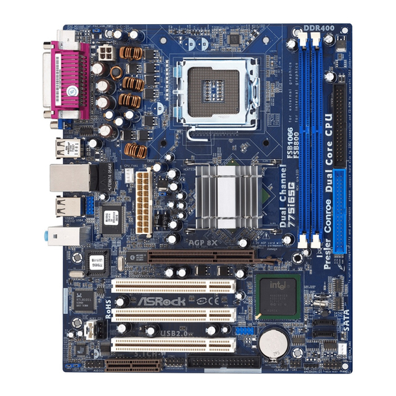
Page 9: Motherboard Layout
1.3 Motherboard Layout 1.3 Motherboard Layout 1.3 Motherboard Layout 1.3 Motherboard Layout 1.3 Motherboard Layout 20.3cm (8.0 in) DDR400 PS2_USB_PWR1 Mouse Keyboard VGA1 USB 2.0 T: USB2 B: USB3 Intel 865G USB 2.0 T: USB4 Chipset B: USB5 AGP8X 1.5V_AGP1 BIOS RoHS PCI 1... -
Page 10: Asrock I/O Plus
1.4 ASRock I/O Plus 1.4 ASRock I/O Plus 1.4 ASRock I/O Plus 1.4 ASRock I/O Plus 1.4 ASRock I/O Plus Parallel Port USB 2.0 Ports (USB01) RJ-45 Port USB 2.0 Ports (USB23) Line In (Light Blue) VGA Port Line Out (Lime) -
Page 11: Installation
Chapter 2 Installation Chapter 2 Installation Chapter 2 Installation Chapter 2 Installation Chapter 2 Installation 775i65G is a Micro ATX form factor (9.6" x 8.0", 24.4 x 20.3 cm) motherboard. Before you install the motherboard, study the configuration of your chassis to ensure that the motherboard fits into it. -
Page 12: Cpu Installation
2.3 CPU Installation 2.3 CPU Installation 2.3 CPU Installation 2.3 CPU Installation 2.3 CPU Installation For the installation of Intel 775-LAND CPU, please follow the steps below. 775-Pin Socket Overview Before you insert the 775-LAND CPU into the socket, please check if the CPU surface is unclean or if there is any bent pin on the socket. - Page 13 For proper inserting, please ensure to match the two orientation key notches of the CPU with the two alignment keys of the socket. Step 2-3. Carefully place the CPU into the socket by using a purely vertical motion. Step 2-4. Verify that the CPU is within the socket and properly mated to the orient keys.
-
Page 14: Installation Of Cpu Fan And Heatsink
Installation of CPU Fan and Heatsink Installation of CPU Fan and Heatsink Installation of CPU Fan and Heatsink Installation of CPU Fan and Heatsink Installation of CPU Fan and Heatsink This motherboard is equipped with 775-Pin socket that supports Intel 775-LAND CPU. Please adopt the type of heatsink and cooling fan compliant with Intel 775-LAND CPU to dissipate heat. -
Page 15: Installation Of Memory Modules (Dimm)
2.5 Installation of Memory Modules (DIMM) 2.5 Installation of Memory Modules (DIMM) 2.5 Installation of Memory Modules (DIMM) 2.5 Installation of Memory Modules (DIMM) 2.5 Installation of Memory Modules (DIMM) This motherboard provides two 184-pin DDR (Double Data Rate) DIMM slots, and supports Dual Channel Memory Technology. -
Page 16: Expansion Slots (Pci,Agp And Amr Slots)
PCI slots: The PCI slots are used to install expansion cards that have the 32-bit PCI interface. AGP slot: The AGP slot is used to install a graphics card. The ASRock AGP slot has a special design of clasp that can securely fasten the inserted graphics card. -
Page 17: Jumpers Setup
2.7 Jumpers Setup 2.7 Jumpers Setup 2.7 Jumpers Setup 2.7 Jumpers Setup 2.7 Jumpers Setup The illustration shows how jumpers are setup. When the jumper cap is placed on pins, the jumper is “Short”. If no jumper cap is placed on pins, the jumper is “Open”. The illustration shows a 3-pin jumper whose pin1 and pin2 are “Short”... -
Page 18: Onboard Headers And Connectors
2.8 Onboard Headers and Connectors 2.8 Onboard Headers and Connectors 2.8 Onboard Headers and Connectors 2.8 Onboard Headers and Connectors 2.8 Onboard Headers and Connectors Onboard headers and connectors are NOT jumpers. Do NOT place jumper caps over these headers and connectors. Placing jumper caps over the headers and connectors will cause permanent damage of the motherboard! FDD connector... - Page 19 USB 2.0 Header ASRock I/O Plus accommo- USB_PWR dates 6 default USB 2.0 ports. If (9-pin USB67) those USB 2.0 ports on the I/O DUMMY (see p.9 No.
- Page 20 1. +5VA is used for audio power only, please don’t connect it to any other power, such as USB. 2. HD (Azalia) audio front panel and AC’97 audio front panel have different pin-definition. Incorrect connection of the audio front panel and the front panel audio header may cause permanent damage to this motherboard.
-
Page 21: Serial Ata (Sata) Hard Disks Installation
Serial A Serial A Serial A Serial A Serial AT T T T T A (SA A (SA A (SA A (SA A (SAT T T T T A) Hard Disks Installation A) Hard Disks Installation A) Hard Disks Installation A) Hard Disks Installation A) Hard Disks Installation This motherboard adopts Intel ICH5 south bridge chipset that supports Serial ATA... -
Page 22: Etup Utility
Chapter 3 BIOS SETUP UTILITY Chapter 3 BIOS SETUP UTILITY Chapter 3 BIOS SETUP UTILITY Chapter 3 BIOS SETUP UTILITY Chapter 3 BIOS SETUP UTILITY Introduction Introduction Introduction Introduction Introduction This section explains how to use the BIOS SETUP UTILITY to configure your system. The BIOS FWH chip on the motherboard stores the BIOS SETUP UTILITY. -
Page 23: Navigation Keys
3.1.2 3.1.2 Navigation Keys Navigation Keys 3.1.2 3.1.2 3.1.2 Navigation Keys Navigation Keys Navigation Keys Please check the following table for the function description of each navigation key. Navigation Key(s) Function Description Moves cursor left or right to select Screens Moves cursor up or down to select items + / - To change option for the selected items... -
Page 24: Cpu Configuration
BIOS SETUP UTILITY Main Advanced H/W Monitor Boot Security Exit Configure CPU Advanced Settings WARNING : Setting wrong values in below sections may cause system to malfunction. CPU Configuration Chipset Configuration ACPI Configuration IDE Configuration PCIPnP Configuration Select Screen Floppy Configuration Select Item SuperIO Configuration Enter Go to Sub Screen... - Page 25 Ratio Actual Value This is a read-only item, which displays the ratio actual value of this motherboard. Ratio CMOS Setting If the ratio status is unlocked, will find this item appear to allow you chang- ing the ratio value of this motherboard. Enhance Halt State All processors support the Halt State (C1).
-
Page 26: Chipset Configuration
3.3.2 3.3.2 3.3.2 Chipset Configuration Chipset Configuration Chipset Configuration Chipset Configuration 3.3.2 3.3.2 Chipset Configuration BIOS SETUP UTILITY Advanced Chipset Configuration Options DRAM Frequency [Auto] 133MHz (DDR266) [Disabled] Flexibility Option 166MHz (DDR333) [Disabled] Configure DRAM Timing by SPD 200MHz (DDR400) [Auto] DRAM CAS# Latency Auto... - Page 27 Graphics Aperture Size It refers to a section of the PCI memory address range used for graphics memory. It is recommended to leave this field at the default value unless the installed AGP card’s specifications requires other sizes. OnBoard LAN This allows you to enable or disable the “OnBoard LAN”...
-
Page 28: Acpi Configuration
3.3.3 3.3.3 ACPI Configuration 3.3.3 ACPI Configuration ACPI Configuration ACPI Configuration 3.3.3 3.3.3 ACPI Configuration BIOS SETUP UTILITY Advanced ACPI Configuration Select auto-detect or disable the STR feature. [Disabled] Suspend To RAM Restore on AC / Power Loss [Power Off] Ring-In Power On [Disabled] PCI Devices Power On... -
Page 29: Ide Configuration
3.3.4 3.3.4 IDE Configuration 3.3.4 IDE Configuration IDE Configuration IDE Configuration 3.3.4 3.3.4 IDE Configuration BIOS SETUP UTILITY Advanced Set [Compatible Mode] IDE Configuration when both Legacy OS (MS-DOS, Win Me / 98SE) [Enhanced Mode] OnBoard IDE Operate Mode and SATA device OnBoard IDE Controller [Both] are used. - Page 30 IDE Device Configuration You may set the IDE configuration for the device that you specify. We will use the “Primary IDE Master” as the example in the following instruction, which can be applied to the configurations of “Primary IDE Slave”, “Sec- ondary IDE Master”, “Secondary IDE Slave”, “SATA1”...
-
Page 31: Pcipnp Configuration
Block (Multi-Sector Transfer) The default value of this item is [Auto]. If this feature is enabled, it will enhance hard disk performance by reading or writing more data during each transfer. PIO Mode Use this item to set the PIO mode to enhance hard disk performance by optimizing the hard disk timing. -
Page 32: Floppy Configuration
3.3.6 3.3.6 3.3.6 Floppy Configuration 3.3.6 3.3.6 Floppy Configuration Floppy Configuration Floppy Configuration Floppy Configuration In this section, you may configure the type of your floppy drive. BIOS SETUP UTILITY Advanced Floppy Configuration Select the type of floppy drive connected to the Floppy A [1.44 MB 3 "] system. -
Page 33: Usb Configuration
Parallel Port Address Use this item to set the address for the onboard parallel port or disable it. Configuration options: [Disabled], [378], and [278]. Parallel Port Mode Use this item to set the operation mode of the parallel port. The default value is [ECP+EPP]. -
Page 34: Hardware Health Event Monitoring Screen
3.4 Hardware Health Event Monitoring Screen Hardware Health Event Monitoring Screen Hardware Health Event Monitoring Screen Hardware Health Event Monitoring Screen Hardware Health Event Monitoring Screen In this section, it allows you to monitor the status of the hardware on your system, including the parameters of the CPU temperature, motherboard temperature, CPU fan speed, chassis fan speed, and the critical voltage. -
Page 35: Boot Screen
3.5 Boot Screen Boot Screen Boot Screen Boot Screen Boot Screen In this section, it will display the available devices on your system for you to config- ure the boot settings and the boot priority. BIOS SETUP UTILITY Main Advanced H/W Monitor Boot Security... -
Page 36: Boot Device Priority
3.5.2 3.5.2 Boot Device Priority Boot Device Priority 3.5.2 3.5.2 Boot Device Priority 3.5.2 Boot Device Priority Boot Device Priority In this section, you may specify the boot sequence from the available devices in your system. BIOS SETUP UTILITY Boot Boot Device Priority Specifies the boot sequence from the... -
Page 37: Exit Screen
3.7 Exit Screen Exit Screen Exit Screen Exit Screen Exit Screen BIOS SETUP UTILITY Main Advanced H/W Monitro Boot Security Exit Exit Options Exit system setup after saving the changes. Save Changes and Exit Discard Changes and Exit F10 key can be used Discard Changes for this operation. -
Page 38: Install Operating System
4.2.5 Contact Information Contact Information Contact Information Contact Information Contact Information If you need to contact ASRock or want to know more about ASRock, welcome to visit ASRock’s website at http://www.asrock.com; or you may contact your dealer for further information.
Need help?
Do you have a question about the 775i65G R2.0 and is the answer not in the manual?
Questions and answers