Table of Contents
Advertisement
Quick Links
Advertisement
Table of Contents

Related Manuals for THORLABS PDA015C2


Summary of Contents for THORLABS PDA015C2
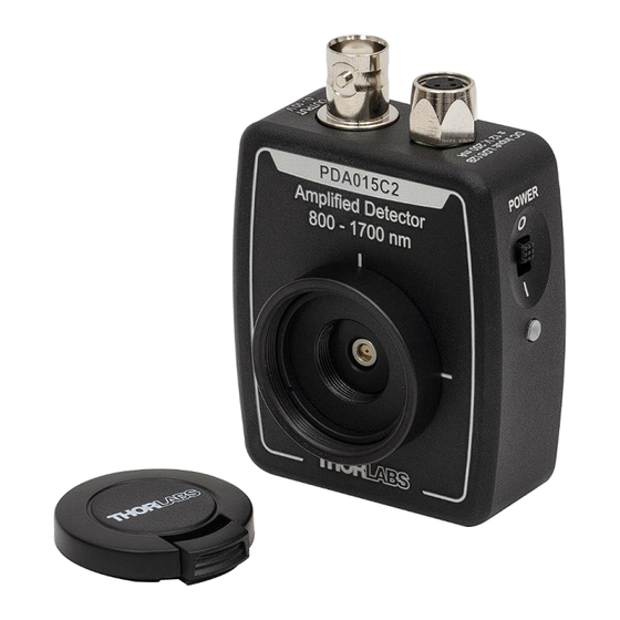
- Page 1 PDA015C2 InGaAs Amplified Fixed Gain Detector User Guide...
-
Page 2: Table Of Contents
Setup Guide ........................3 Chapter 4 Operation ........................5 Chapter 5 Troubleshooting ......................7 Chapter 6 Specifications ....................... 8 Chapter 7 Certificate of Conformance ..................15 Chapter 8 Warranty and RMA Information ................. 16 Chapter 9 Thorlabs Worldwide Contacts ..................17... -
Page 3: Chapter 1 Safety
The statement for other products will appear in the accompanying documentation. Inputs and outputs must only be connected with shielded connection cables. Only with written consent from Thorlabs may changes to single components be carried out or components not supplied by Thorlabs be used. -
Page 4: Chapter 2 Description
The LDS12B± 12 VDC power supply is included with each amplified photodetector, and a switch on the power supply can be toggled to select the appropriate input voltage (100, 120, or 230 VAC ). The PDA015C2 detector housing includes a removable threaded coupler (SM1T1) and retaining ring (SM1RR) that are compatible with any of Thorlabs’... -
Page 5: Chapter 3 Setup Guide
8. The maximum output of the PDA015C2 detector is 10 V for high impedance loads and 5 V for 50 Ω loads. The output signal should be below the maximum output voltage to avoid saturation. If necessary, use external neutral density filters to reduce the input light level. - Page 6 Chapter 3: Setup Guide Caution! The PDA015C2 detector was designed to allow maximum accessibility to the photodetector by having the front surface of the PD TO-can nearly flush with the outside of the PDA housing. When using fiber adapters, make sure that the fiber ferrule does not crash into the TO-can window. Failure to do so may cause damage to the TO-can window and/or the fiber.
-
Page 7: Chapter 4 Operation
1 nA up to many μA. In the case of the PDA015C2 detector, in most cases the dark current is small enough to ignore (<3 nA). - Page 8 CG are the same. For a 50 Ω external load, the actual CG is a factor of two smaller than the CG. It is for this reason that the maximum output of the PDA015C2 detector is 10 V for high impedance loads and 5 V for 50 Ω...
-
Page 9: Chapter 5 Troubleshooting
InGaAs Amplified Fixed Gain Detector Chapter 5: Troubleshooting Chapter 5 Troubleshooting Problem Suggested Solutions Verify that the power is switched on and all connections are secure. Verify that the power indicator LED on the power supply and the LED on the PDA are both on. There is no signal response. -
Page 10: Chapter 6 Specifications
InGaAs Amplified Fixed Gain Detector Chapter 6: Specifications Chapter 6 Specifications Electrical Specifications Detector InGaAs PIN Photodiode Active Area Ø150 µm (0.018 mm Wavelength Range λ 800 to 1700 nm Peak Wavelength λ 1550 nm Optical Input Power, Max 180 µW (��... - Page 11 InGaAs Amplified Fixed Gain Detector Chapter 6: Specifications General Specifications On/Off Switch Slide BNC (DC Coupled) Output 50 Ω Impedance 2.79" x 1.96" x 0.89" Package Size (70.9 mm x 49.8 mm x 22.5 mm) PD Surface Depth 0.16" (4.1 mm) Weight, Detector Only 0.1 kg SM1T1 Coupler...
- Page 12 InGaAs Amplified Fixed Gain Detector Chapter 6: Specifications Responsivity Figure 3 Typical Responsivity of the PDA015C2 Detector Temporal Response 1.0 ns -0.2 Figure 4 Typical Impulse Response of the PDA015C2 Detector Page 10 TTN321265-D02...
- Page 13 InGaAs Amplified Fixed Gain Detector Chapter 6: Specifications Figure 5 Typical Step Response of the PDA015C2 Detector Frequency Response -3 dB Bandwidth 100 200 300 400 500 600 700 800 900 1000 Figure 6 Typical Frequency Response of the PDA015C2 Detector Rev.
- Page 14 Noise Spectrum Typical Noise Spectrum 100 200 300 400 500 600 700 800 900 1000 Frequency (MHz) Figure 8 Typical Noise Spectrum for the PDA015C2 Detector, Measured with a 50 Ω Load and 900 kHz Resolution Bandwidth Page 12 TTN321265-D02...
- Page 15 ) can be calculated by multiplying the data in this graph by the conversion gain and the square root of the bandwidth. Figure 9 Typical NEP for the PDA015C2 detector at the Maximum Responsivity Wavelength, Measured with a 50 Ω Load Rev. A, June 30, 2023...
- Page 16 InGaAs Amplified Fixed Gain Detector Chapter 6: Specifications Mechanical Drawing Page 14 TTN321265-D02...
-
Page 17: Chapter 7 Certificate Of Conformance
InGaAs Amplified Fixed Gain Detector Chapter 7: Certificate of Conformance Chapter 7 Certificate of Conformance Rev. A, June 30, 2023 Page 15... -
Page 18: Chapter 8 Warranty And Rma Information
Waste treatment is your own responsibility. “End of life” units must be returned to Thorlabs or handed to a company specializing in waste recovery. Do not dispose of the unit in a litter bin or at a public waste disposal site. It is the user’s responsibility to delete all private data stored on the device prior to disposal. -
Page 19: Chapter 9 Thorlabs Worldwide Contacts
InGaAs Amplified Fixed Gain Detector Chapter 9: Thorlabs Worldwide Contacts Chapter 9 Thorlabs Worldwide Contacts For technical support or sales inquiries, please visit us at for our most up-to-date www.thorlabs.com/contact contact information. USA, Canada, and South America UK and Ireland Thorlabs, Inc. - Page 20 www.thorlabs.com...
Need help?
Do you have a question about the PDA015C2 and is the answer not in the manual?
Questions and answers