Table of Contents
Advertisement
Quick Links
INSTALLATION GUIDE
V1.0
Issuing Date
2024-03-07
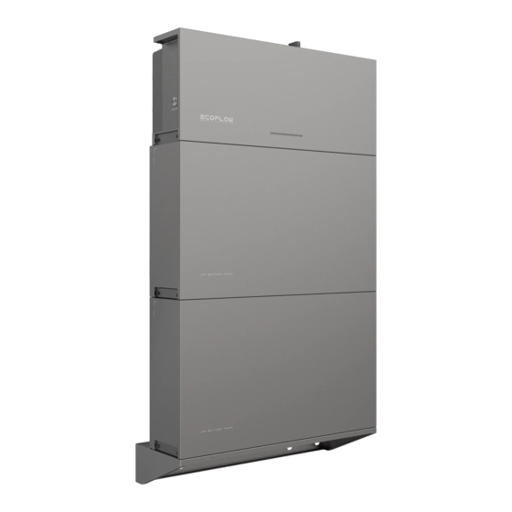
ECOFLOW POWEROCEAN SINGLE-
PHASE
Home Solar Bat ter y Solution
For the latest documents, please scan the QR code or visit:
https://enterprise.ecoflow.com/eu/documentation
IMPORTANT
• Before installing, operating, and maintaining the equipment, read and
follow up Installation Guide and Safety Instructions.
Advertisement
Table of Contents

Related Manuals for EcoFlow POWEROCEAN SINGLE-PHASE


Summary of Contents for EcoFlow POWEROCEAN SINGLE-PHASE
- Page 1 INSTALLATION GUIDE V1.0 Issuing Date 2024-03-07 ECOFLOW POWEROCEAN SINGLE- PHASE Home Solar Bat ter y Solution For the latest documents, please scan the QR code or visit: https://enterprise.ecoflow.com/eu/documentation IMPORTANT • Before installing, operating, and maintaining the equipment, read and follow up Installation Guide and Safety Instructions.
-
Page 2: Table Of Contents
Installing COM Connector With Shorting Wire (Optional) Installing Emergency Stop (EPO) Connecting PV Input Cables Connecting Smart Meter Connecting to Internet Installing trim cover Installing EcoFlow IOT Dongle ESS (Optional) Installing EcoFlow 4G Dongle ESS(EU) 20 System Commissioning Checking before Power-On System Power-On... -
Page 3: Safety Instructions
• Before installing, operating, and maintaining the equipment, read and follow up Installation Guide and Safety Instructions. • Personnel who plan to install or maintain EcoFlow equipment must receive thorough training, understand all necessary safety precautions, and be able to correctly perform all operations. -
Page 4: Preparing Tools And Instruments
Preparing Tools and Instruments ·ESSENTIAL TOOLS Multimeter Hammer drill Screwdriver (DC voltage measurement (with a drill bit of 8mm) Electrical Screwdriver Torque socket of 10mm Mallet (PH3) range ≥ 1000 V DC) Crimping tool Cable cutter Crimping tool Wire strippers RJ45 Crimping tool (for tubular terminal) Wrench (14mm) - Page 5 ·ECOFLOW POWEROCEAN LFP BATTERY ×1 ×2 ×8 ×2 Battery T-shaped mounting piece(M6) EcoFlow PowerOcean LFP Battery Battery L-shaped mounting piece Screws(M5*12) Expansion bolt(M6*60) ·ECOFLOW POWEROCEAN LFP BATTERY BASE ×1 ×4 ×2 ×1 Marking-off template for Battery base Adjustable feet Expansion bolt(M6*60) battery...
-
Page 6: Installation Environment Requirements
System Installation WARNING • The installation and use environment must meet relevant international, national, Installation Environment and local standards for lithium batteries, and are in accordance with the local Requirements laws and regulations. NOTICE • When installing the equipment in a garage, keep it away from the drive way. •... -
Page 7: Installing Battery
DANGER • When drilling holes, avoid the water pipes and power cables buried in the wall and Installing under the floor. Battery • When drilling holes, protect the battery base from shavings or dust. • Before installing the battery, make sure that the click-on terminals on the top and bottom of the battery are free of foreign objects or any liquid. - Page 8 ·WITHOUT ADJUSTABLE FEET ×1 65-85mm 5.0 N·m 10 mm M6*60 ❷ (PH3) ❶ ×2 ×1 ×2 1.3 N·m M5*12 M6*60 ❶ ❷ ❷ 2.5 N·m 5.0 N·m ❶...
-
Page 9: Installing Inverter
×2 ×1 ×2 ×2 ×2 ×1 Installing Inverter ×1 1.3 N·m M5*12 M5*12 ❶ ❷ 1.3 N·m ❸... -
Page 10: System Overview
Inverter Battery Battery WIFI Ethernet RS485 4G (optional) - (Optional) EcoFlow 4G Dongle ESS(EU) • For 4G network • Sold separately - EcoFlow IOT Dongle ESS • For wireless network - Smart meter • Supports power sampling • Sold separately - (Optional) Emergency Stop (EPO) •... -
Page 11: System Wiring Diagram
NOTICE • N and PE wiring via GRID and BACKUP ports of the inverter vary based on the System Wiring regulation requirements of different regions. Refer to the specific requirements of Diagram local regulations. a. N and PE cables are connected together in the Main Panel for wiring. NOTICE •... -
Page 12: Connecting Pe Cables
NOTICE • Ensure that the PE cable is connected securely. Connecting • Wrap the wire crimping area with heat shrink tubing or insulation tape. The heat PE Cables shrink tubing is used as an example. • When using a heat gun, protect the equipment from being scorched. •... -
Page 13: Connecting Backup Cables
×1 1.2 N.M GRID Terminal GRID Terminal 1.2 N.M Remove protective cap with a screwdriver GRID Connector CAUTION Connecting • Before installing, operating, and maintaining the equipment, always disconnect it from all power. • Do not connect the BACKUP connector to the GRID terminal of the inverter. BACKUP Cables •... -
Page 14: Installing Com Connector With Shorting Wire
NOTICE • COM terminal supports logic interface connection. Logic interface is required by Installing some local regulations that can be operated by a simple switch or contactor. COM Connector With • When the switch is closed, the inverter can operate normally.When the switch is Shorting Wire opened, the inverter will reduce its active power to zero within 5s. -
Page 15: Optional) Installing Emergency Stop (Epo)
NOTICE • Before installing EPO, please remove the shorting wire between PIN14 and PIN16. (Optional) Installing • For more details about Emergency Stop, please refer to its user manual. Emergency Stop (EPO) ×1 D:4-8mm D:8-11mm ❷ ❶ Remove protective with a screwdriver Click... -
Page 16: Connecting Pv Input Cables
DANGER • Before connecting the PV input cables, ensure AC switch connected to the inverter and the Connecting PV SWITCH on the inverter are OFF. Failing to do so may result in electric shocks. PV Input Cables • The PV string will generate lethal high voltage when exposed to sunlight. Disconnect the PV cable of PV string before connecting DC power. - Page 17 REMOVE SOLARLOK SAFE-TE CONNECTORS ❶ ❷ ❶ ❷ CONNECT TO THE INVERTER. Set the multimeter to DC gear to measure the voltage at the DC position. If the voltage is a negative value, the PV input polarity is incorrect and needs correction. If the voltage is greater than 1000 V, too many PV modules are configured to the same string. Remove some PV modules.
-
Page 18: Connecting Smart Meter
NOTICE • It is recommend to use of CAT5 or higher rating network cable. Connecting • Smart meter is sold separately, which has been preset parameters before delivered. Do Smart Meter not modify the relevant parameters. • The compatibility of this product with smart meters may vary by regions and versions. For detailed instructions on the installation and wiring scheme of the smart meter for this product, please refer to the guide that comes together with the meter. - Page 19 SMART METER (WITH CT) INSTALLATION METER SAMPLING Grid L Access the home main line and connect the smart Grid N meter as shown in the diagram. RS485 A RS485 B METER COMMUNICATION Connect communication port A, B on the meter to the METER port of inverter.
-
Page 20: Connecting To Internet
NOTICE Connecting to • Use shielded CAT 5 or higher rating network cable for stable connection. Internet ·METHOD 1: VIA A WIRED NETWORK ❷ ❹ ❶ ❸ Remove protective cap Remove protective cap Both ends of the network cable use the T568B wiring standard. ×1 T568B T568B... -
Page 21: Installing Trim Cover
❷ ❶ Remove protective cap Remove protective cap ❸ USB-C NOTICE • For more details about EcoFlow 4G Dongle ESS(EU), please refer to its (Optional) Installing EcoFlow user manual. 4G Dongle ESS(EU) ❷ ❶ Remove protective cap Remove protective cap ❸... -
Page 22: Checking Before Power-On
Converter is faulty. Abnormal converter communication. NOTICE • If the LED indicates a faulty status, visit the EcoFlow Pro app to retrieve the error code for troubleshooting. 2 0 |... -
Page 23: System Commissioning
You can connect to the system via Bluetooth or Wi-Fi. a. Connect to the system via Bluetooth. Click Add System to automatically search for bluetooth devices nearby, and click EcoFlow PowerOcean Single Phase to connect, then click Complete to proceed. - Page 24 3. After successfully connected your phone to "PowerOcean_ Click WiFi,select the appropriate WiFi name and enter xxxx", tap the "EcoFlow Pro" on the top left of your the password and click continue. phone's Wi-Fi setting page to shift back and proceed to commissioning.
- Page 25 Method 3: 4G 1. Install a nano SIM card to the EcoFlow 4G Dongle ESS(EU). 2. Install the dongle onto the USB port (4G) of the inverter. 3. Activate your SIM card through App. For more details about EcoFlow 4G Dongle ESS(EU), please refer to its user manual.
- Page 26 Frequency Protection parameters, Reactive Power parame- Device Setting. ters and other parameters. (Please follow local regulations, If there is a firmware update available for the EcoFlow if you need to change any of these parameters, please PowerOcean system, the update page will pop up contact your local power organization first.)
- Page 27 Solar generation may fluctuate. • After manually adding device EcoFlow PowerOcean using the EcoFlow User App, users scan the home owner access QR code to bind it. (OPTIONAL) ADD DEVICE TO THE SYSTEM (Optional) Tap "Add Device" to integrate devices into this system, such as SG READY certified Heat Pump or charging pile etc., and setup relevant parameters.
-
Page 28: How Users Add Devices
How Users Add Devices 1. DOWN AND INSTALL ECOFLOW USER APP (FOR USER ONLY) Scan the QR code or download at: https://download.ecoflow.com/app EcoFlow App 2. CREATE NEW ACCOUNT AND LOG IN. 3. ADD DEVICE MANUALLY. Raccolta carta 2 6 |...
Need help?
Do you have a question about the POWEROCEAN SINGLE-PHASE and is the answer not in the manual?
Questions and answers