
Related Manuals for SMART Board MX (V5) Series


Summary of Contents for SMART Board MX (V5) Series
- Page 1 SMART Board ® MX (V5) | MX (V5) Pro series interactive displays Installation and maintenance guide IDX55-5 IDX65-5 IDX75-5 IDX86-5 Was this document helpful? smarttech.com/docfeedback/171897...
- Page 2 Trademark notice SMART Board, SMART Notebook, SMART TeamWorks, SMART Meeting Pro, Lumio, Object Awareness, smarttech, the SMART logo and all SMART taglines are trademarks or registered trademarks of SMART Technologies ULC in the U.S. and/or other countries. Google, Android, Chrome, and Google Drive are trademarks of Google Inc. Microsoft, Windows, and OneDrive are either registered trademarks or trademarks of Microsoft Corporation in the United States and/or other countries.
-
Page 3: Table Of Contents
About this guide About the display More information Chapter 2 Installing and maintaining the display Is this the first time you’ve installed or maintained a SMART Board interactive display? Installing the display Installing SMART OPS appliances Connecting to a network Connecting power and turning on the display for the first time Adjusting the display’s settings... - Page 4 Contents Asynchronous messages Appendix B Enrolling the display in SMART Remote Management Certification and compliance docs.smarttech.com/kb/171897...
-
Page 5: Chapter 1 Welcome
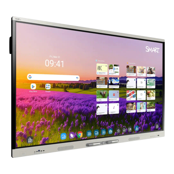
MX (V5) or MX (V5) Pro series interactive display is the hub of your classroom or meeting room. About this guide This guide explains how to install and maintain a SMART Board MX (V5) or MX (V5) Pro series interactive display. It includes the following information: ... - Page 6 If you need to install or maintain the display, take this tour to familiarize yourself with its components: Component Description In this guide iQ is the SMART Board MX (V5) and MX (V5) Pro SeePage 13 series interactive display’s embedded Android SeePage 14 operating system.
- Page 7 Chapter 1 Welcome Component Description In this guide Pens The display comes with two pens, which users can use to write or draw on the screen. Replace a pen if its nib becomes worn to prevent damage to the screen or impairment of pen and finger detection.
- Page 8 In addition to this guide, SMART provides other documents for the display in the Support section of the SMART website (smarttech.com/support). Scan the QR code on page 2 to view links to SMART Board MX (V5) and MX (V5) Pro series interactive display documents and other support resources.
-
Page 9: Chapter 2 Installing And Maintaining The Display
Is this the first time you’ve installed or maintained a SMART Board interactive display? If you haven’t installed or maintained a SMART Board interactive display before, refer to the SMART Board interactive display installation and maintenance hub for general instructions and best practices for installing and maintaining a display, including: ... -
Page 10: Installing The Display
Refer to the illustrated installation instructions included with the display for specific information about installing it. If you’ve misplaced these instructions, they’re also available online. See SMART Board MX (V5) and MX (V5) Pro series illustrated installation instructions (docs.smarttech.com/kb/171930) docs.smarttech.com/kb/171897... -
Page 11: Installing Smart Ops Appliances
Seesupport.smarttech.com/accessories/computing-modules-and-appliances Caution Only SMART-provided OPS appliances are supported in SMART Board interactive displays. Third-party OPS appliances are not supported, and their use can lead to poor performance or damage to the display. Do not install or remove the OPS appliance while the display is turned on. First make sure the power switch on the back of the display beside the AC power inlet is in the OFF (O) position. - Page 12 Chapter 2 Installing and maintaining the display The display requires an internet connection for downloading software and firmware updates, and a number of the iQ apps require a network connection as well. You can connect to the network with Wi-Fi or with an Ethernet cable attached to one of the RJ45 jacks.
-
Page 13: Connecting Power And Turning On The Display For The First Time
Chapter 2 Installing and maintaining the display Connecting power and turning on the display for the first time The final step in installing and configuring the display is to connect power, turn the display on, and configure iQ following the steps in the wizard. To connect the display to power ... -
Page 14: Adjusting The Display's Settings
Chapter 2 Installing and maintaining the display Notes Touch is not available immediately after waking or turning on the display. Wait a few seconds, and then the display will respond to touch. If a USB drive is connected to the display’s service port receptacle, do not remove the USB drive. The USB drive may contain an important firmware update. -
Page 15: Chapter 3 Connecting Computers And Other Devices
Chapter 3 Connecting computers and other devices Installing SMART software Connecting room computers and guest laptops Viewing a connected computer’s input Setting a connected computer’s resolution and refresh rate Connecting other devices Connecting USB drives, peripherals, and other devices Connecting an external display Connecting an external audio system Connecting room control systems Connector diagrams... -
Page 16: Installing Smart Software
Installing SMART software The display comes with SMART software that you can install on connected room computers and guest laptops. Other SMART software is optional. Software type SMART Board MX (V5) series SMART Board MX (V5) Pro series Included SMART Notebook... - Page 17 Chapter 3 Connecting computers and other devices USB-C 1 Video/audio/touch Connector USB-C 1 Standard USB 3.2 Gen 1×1 (as DFP) Display Port 1.2.4-lane (as UFP) USB-C 2 Video/audio/touch Connector USB-C 2 Standard USB 3.2 Gen 1×1 (as DFP) Display Port 1.2.4-lane (as UFP) docs.smarttech.com/kb/171897...
- Page 18 Chapter 3 Connecting computers and other devices HDMI 1 Video/audio Connector HDMI 1 Standard HDMI 2.1 Touch Connector Touch (USB Type-B) Standard USB 3.2 Gen 1 HDMI 2 Video/audio Connector HDMI 2 Standard HDMI 2.1 Touch Connector Touch (USB Type-B) Standard USB 3.2 Gen 1 docs.smarttech.com/kb/171897...
- Page 19 Chapter 3 Connecting computers and other devices HDMI 3 Video/audio Connector HDMI 3 Standard HDMI 2.1 Touch Connector Touch (USB Type-B) Standard USB 3.2 Gen 1 HDMI 4 Video/audio Connector HDMI 4 Standard HDMI 2.1 Touch Connector Touch (USB Type-B) Standard USB 3.2 Gen 1 The HDMI 4 and VGA inputs share a USB Type-B receptacle.
-
Page 20: Viewing A Connected Computer's Input
If a connected computer reports “Too many USB hubs” or “cannot start (code 10),” see the knowledge base article, SMART Board interactive displays and USB tier structure use. Viewing a connected computer’s input 1. Connect the computer to the display. -
Page 21: Setting A Connected Computer's Resolution And Refresh Rate
Chapter 3 Connecting computers and other devices Press Input on the front control panel. Press Input on the remote control. The input selection menu appears. 3. Tap the computer’s input menu option. Setting a connected computer’s resolution and refresh rate This table presents the recommended resolutions and refresh rates for the display’s USB-C and HDMI inputs: Resolution... -
Page 22: Connecting Other Devices
Chapter 3 Connecting computers and other devices Resolution Input aspect ratio Mode Refresh rate 1280 × 1024 SXGA 60 60.020 Hz 1024 × 768 XGA 60 60.004 Hz XGA 70 70.069 Hz XGA 75 75.029 Hz 800 × 600 SVGA 60 60.317 Hz SVGA 72 72.188 Hz... -
Page 23: Connecting Usb Drives, Peripherals, And Other Devices
Chapter 3 Connecting computers and other devices Connecting USB drives, peripherals, and other devices The display includes the following USB receptacles. You can connect USB drives, peripherals (such as keyboards), and other devices to these receptacles and use the devices with iQ, connected computers, and OPS modules installed in the OPS accessory slot. -
Page 24: Connecting An External Display
Chapter 3 Connecting computers and other devices Connecting an external display You can connect an external display to models that have an HDMI Out connector on the connector panel. The external display will show the same image. This is useful when you’re using the display in an auditorium or other large space where it would be beneficial to have a second display. -
Page 25: Connecting Room Control Systems
Chapter 3 Connecting computers and other devices In addition to the Stereo 3.5 mm Out connector, the display provides a Sony/Philips Digital Interface (S/PDIF) Out connector. S/PDIF is a digital audio transmission medium. You need an audio system that has an S/PDIF input to decode this connection to analog. -
Page 26: Connector Diagrams
Chapter 3 Connecting computers and other devices Connector diagrams Side and bottom connector panels This diagram and table present the connectors on the display’s side and bottom connector panels: Side Bottom Connector Connects to Notes 1 microSD microSD card This connector features a security cover to prevent theft of an installed microSD card. -
Page 27: Front Connector Panel
Chapter 3 Connecting computers and other devices Connector Connects to Notes 7 HDMI 2.1 In HDMI 2 input This connector supports HDMI (video and audio) ARC (Audio Return Channel) and eARC (Enhanced Audio Return Channel), which allow audio signals to travel between the display and the connected device and improve audio quality as a result. - Page 28 Chapter 3 Connecting computers and other devices Connector Connects to Notes 1 USB Type-C USB Type-C 1 input SeePage 16 2 HDMI In HDMI 3 input SeePage 16 (video and audio) 3 USB 3.2 Gen 1 Type-B SeePage 16 HDMI 3 input (touch) 4 ...
-
Page 29: Chapter 4 Troubleshooting
The serial number is on a label located on the left side of the display (pictured). Tip Scan the QR code on the label to view the SMART Board MX (V5) and MX (V5) Pro series interactive display support pages on the SMART website. docs.smarttech.com/kb/171897... -
Page 30: Appendix A Managing The Display Using Rs-232
Appendix A Managing the display using RS-232 Configuring the serial interface settings Commands and responses Power state commands Input commands Brightness commands Freeze commands Screen shade commands Speaker commands Microphone array commands Firmware version commands Model number commands Serial number commands Part number commands Asynchronous messages You can connect an RS-232 cable from a computer or a control... -
Page 31: Configuring The Serial Interface Settings
Appendix A Managing the display using RS-232 Configuring the serial interface settings Configure the computer or control system’s serial interface before sending commands to the display. 1. Turn on the display. 2. If you’re using a terminal application on a computer, activate local echo to see what you’re typing and sending to the display. -
Page 32: Commands And Responses
Appendix A Managing the display using RS-232 Commands and responses To access display information or to adjust display settings using the room control system, send a command after the command prompt (>), send a carriage return character or press ENTER, and then wait for the response from the display. - Page 33 Appendix A Managing the display using RS-232 To assign a value to a setting Use a set command. This example sets the volume to 65: >set volume=65 volume=65 > To increase or decrease the value of a setting Use the set command to increase or decrease the value by a designated number. This example increases the volume by 5: >set volume+5 volume=70...
-
Page 34: Power State Commands
Appendix A Managing the display using RS-232 Power state commands Get command Set command Response get powerstate set powerstate[Value] powerstate=[Value] Where [Value] is one of the following: Where [Value] is one of the following: =standby standby ... -
Page 35: Freeze Commands
Appendix A Managing the display using RS-232 Freeze commands Get command Set command Response get videofreeze set videofreeze[Value] videofreeze=[Value] Where [Value] is one of the following: Where [Value] is one of the following: =off Screen shade commands Get command Set command Response... -
Page 36: Firmware Version Commands
Appendix A Managing the display using RS-232 Firmware version commands Get command Response get fwversion fwversion=[Value] Where [Value] is the firmware version. Model number commands Get command Response get modelnum modelnum=[Value] Where [Value] is one of the following: SBID-MX055-V5 ... - Page 37 Appendix A Managing the display using RS-232 Change Asyncronous message Display power state #powerstate=[Value] Where [Value] is one of the following: standby Input selection #input=[Value] Where [Value] is one of the following: hdmi1 hdmi2 hdmi3 ...
- Page 38 Appendix B Enrolling the display in SMART Remote Management Your SMART Board MX (V5) or MX (V5) Pro series interactive display has a built-in feature that enables you to enroll the display with your organization’s SMART Remote Management account. When you enroll the display, you can use SMART Remote Management to centrally control the display’s features and settings, such as: ...
- Page 39 Certification and compliance Caution Electronic (e-label) information Any changes or modifications not expressly approved by Regulatory information is available in the display’s settings. the party responsible for compliance could void the user’s From the Home screen, tap Settings About Regulatory authority to operate this equipment.
- Page 40 Certification and compliance L’utilisation sur les plates-formes énergétiques, les autos, les Innovation, Science and Economic train, les vaisseaux navigateurs et les avions sera interdite, Development Canada statement sauf sur les gros appareils volant au-dessus de 3 048 m (10 000 pieds). This device complies with RSS-247 and RS-248 of the Innovation, Science and Economic Development Canada Ces appareils ne doivent pas être utilisés pour contrôler des...
- Page 41 Certification and compliance Seedtsc.ca.gov/hazardouswaste/perchlorate Japan VCCI Class A statement – applicable only to models certified for sale in Japan こ の装 置は、 ク ラ スA情報 技術 装置です。 こ の装 置を家庭 環境 で 使用 すると 電 波妨 害を引き起 こ すこ と があり ます。 こ の場 合には使 用者...
- Page 42 SMART Technologies smarttech.com/support smarttech.com/contactsupport docs.smarttech.com/kb/171897...
Need help?
Do you have a question about the MX (V5) Series and is the answer not in the manual?
Questions and answers