Table of Contents
Advertisement
Quick Links
Advertisement
Table of Contents

Related Manuals for Copeland 814-3550


Summary of Contents for Copeland 814-3550
- Page 1 USER MANUAL Wireless Module System Installation and Operation User Manual...
- Page 2 Copeland 1065 Big Shanty Road NW, Suite 100 Kennesaw, GA 30144 USA 770-425-2724 • 1-800-829-2724 www.copeland.com Email: ColdChain.TechnicalServices@copeland.com...
-
Page 3: Table Of Contents
4.2. Module Advanced Settings ................................24 4.2.1. Replacing a Module......................................... 24 4.2.2. Updating a Module Configuration ..................................24 APPENDIX A - TROUBLESHOOTING ....................... 25 Installation ........................................25 Alarm ..........................................29 Communication ......................................31 026-1734 R4 Wireless System Module ©2024 Copeland LP. -
Page 4: Introduction
• Strong 902MHz signal able to pass through most walk-ins. objects with proper layout. • Compatible with all Copeland E2 and Site • Simple installation with Learn and Test button. Supervisor products for remote alarming and • Range analysis and diagnostics integrated into the E2 reporting. -
Page 5: Wireless Gateway Specifications
Wireless Gateway Specifications Figure 1-2 - Wireless Gateway P/N 814-3550 Figure 1-3 - Wireless Gateway Board Table 1-1 - Wireless Gateway Specifications Wireless Gateway Specs Power 24VAC, 10VA Communications RS485 Status (Green) Alarm (Red) LED Indicators RF Msg (Yellow) Check (Blue) 32°F to 122°F... -
Page 6: Wireless Module Specifications
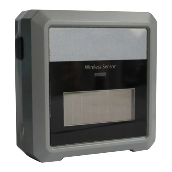
Blue “Check” LED: Blinks once every 0.5 secs when system is being checked for proper operation. Figure 1-4 - Wireless Module Dimensions Wireless Module Specifications Figure 1-6 - Wireless Module Inside Enclosure Figure 1-5 - Wireless Module P/N 814-36xx 026-1734 R4 Wireless Module System ©2024 Copeland LP. -
Page 7: Wireless Module Functionality
The green LED will blink once if the battery voltage is greater than or 2.6V and less than 2.8V(marginal battery). • The green LED will not blink if the battery voltage is less than 2.6V(replace battery). 026-1734 R4 Wireless Module System ©2024 Copeland LP. -
Page 8: Ordering Information
Wireless Module 868MHz with User Selected Inputs; Clean Mode 813-3653 Wireless Module 868MHz, 3 Temp; Clean Mode with Molex Connector 501-1121 Temp Sensor, General Purpose 508-9101 Temp Sensor, Product Simulator 201-1160 Temp Sensor, NSF 026-1734 R4 Wireless Module System ©2024 Copeland LP. -
Page 9: Radio Signal Basics
Device should be placed away from wall corners. Figure 1-10 - Overlapping Coverage Area Figure 1-13 - Central Module Placement • Signals are decreased by specific materials, people or objects in the path. 026-1734 R4 Wireless Module System ©2024 Copeland LP. - Page 10 Signal should be transmitted as directly as possible Avoid Obstacles Using a Repeater Figure 1-17 - through the wall and may require the use of a repeater. Figure 1-15 - Direct Transmission Through a Wall 026-1734 R4 Wireless Module System ©2024 Copeland LP.
-
Page 11: Installation
1. Conduct a site survey to help determine the best location for access points and sensors. You will need the following: • Floor plan. • Drawing compass. • Architect’s scale, tape measure, or laser-distance measuring device. 026-1734 R4 Wireless Module System ©2024 Copeland LP. -
Page 12: Install Gateway Power And Network Cable
Figure 2-2 - Connecting the Gateway to the RS485 Network Termination should only be done at the two end points of the network. Set termination as appropriate: Figure 2-3 - Wireless Gateway Network Wiring 026-1734 R4 Wireless Module System ©2024 Copeland LP. -
Page 13: Set Up And Commissioning
Figure 3-3 - Network Summary Screen 2. After adding the Gateway, go to the Network Summary screen and select the Wireless GW, and then commission , F4: Commission). 026-1734 R4 Wireless Module System ©2024 Copeland LP. -
Page 14: Gateway Settings
Fail Delay: Time with no updates before a sensor is marked as failed. ○ Range 0:10:00 – 2:00:00 (10 min - 2 hrs) • Default 60 (60 min) Figure 3-5 - MODBUS Address Configuration Figure 3-6 - Wireless Gateway Setup 026-1734 R4 Wireless Module System ©2024 Copeland LP. -
Page 15: Set Up And Commissioning Modules In E2
2.Arrow down to 30 Sec Update as shown in Figure 3-10 In this example, two RF Modules were added. and enter Y for Yes. Figure 3-8 - Add Number of RF Module Change RF Module 30 Sec Update Figure 3-10 - 026-1734 R4 Wireless Module System ©2024 Copeland LP. - Page 16 , 1. Commission Device). will display Commissioned and then Good. Figure 3-15 - Commissioned Wireless Module Figure 3-12 - Commission Device The application will enter Learning mode. Figure 3-13 - RF Module Learning Mode 026-1734 R4 Wireless Module System ©2024 Copeland LP.
-
Page 17: Rf Module Status On E2
Hours on battery is shown in the Module Summary screen. The battery will last for 17,100 hours of use. The battery is still within acceptable range if the voltage is 2.90 or higher. Figure 3-18 - Check Signal Reception 026-1734 R4 Wireless Module System ©2024 Copeland LP. -
Page 18: Hours On Battery
1 Bar >= -95 will result in < 70% and cause OPEN Module alarms FAIL Most likely reception rates 0 Bars < -95 will result in < 50% and cause OPEN Module alarms 026-1734 R4 Wireless Module System ©2024 Copeland LP. -
Page 19: E2 Wireless Advanced Settings
1. Go to the Gateway main page ( Press , 9. Application Commands from the 229. Wireless Gateway). Actions Menu. Figure 4-2 - Actions Menu Select 2. Send E2 Cfg to Device Figure 4-4 - Wireless Gateway Main Page 026-1734 R4 Wireless Module System ©2024 Copeland LP. -
Page 20: Module Advanced Settings
Actions Menu. Select 2. Commission-Replace. This will inform the Gateway to remove the existing Module from its database before the start of commissioning (Learning) the replacement Module. Figure 4-7 - RF Module Replace 026-1734 R4 Wireless Module System ©2024 Copeland LP. -
Page 21: Appendix A - Troubleshooting
F4: Look up to select the area controller, application and input. Figure A-1 - Pointing Global Data Indoor Humidity to Module Humidity Sensor Using UltraSite Figure A-2 - Pointing Module Temp Probes to Case Temp Inputs Using E2 Terminal Mode 026-1734 R4 Wireless Module System ©2024 Copeland LP. - Page 22 If the Module is positioned over 100 feet from the Gateway, the signal will be too low to receive signals from the connected sensors. If the signal reception is 1 or 2 Bars when commissioning the Modules, a repeater is needed. Part Number Power Supply 814-3560 12 to 40VDC 814-3570 120 to 277VAC, 50/60Hz 026-1734 R4 Wireless Module System ©2024 Copeland LP.
- Page 23 The Repeater automatically links to the device and repeats the transmission once it is installed. Once installed, the SSI Signal Strength should improve to 3 or 4 Bars. Figure A-5 - SSI Signal Strength Reading Should Improve with the Repeater Installed 026-1734 R4 Wireless Module System ©2024 Copeland LP.
- Page 24 For the User Selectable Module (P/N 814-3600) you will then need to reconfigure the sensor inputs. Select the C2: Config tab in Module Setup and select the sensor type for each input. Figure A-6 - Changing 30 Sec Update on General Tab of Module Setup 026-1734 R4 Wireless Module System ©2024 Copeland LP.
-
Page 25: Alarm
De-select the sensor inputs that are not in use by either clicking the checkmark (in UltraSite) or typing N (E2 Terminal Mode). Figure A-7 -Removing the Inactive Inputs Using UltraSite Tracking When the Module is Running On a Battery. Figure A-8 - Removing the Inactive Inputs in E2 Terminal Mode 026-1734 R4 Wireless Module System ©2024 Copeland LP. - Page 26 Figure A-9 - Hours on Battery When Returning to Solar Cell Power Figure A-10 - Hours on Battery Resumes Counting Up Hours When Back on Battery Power 026-1734 R4 Wireless Module System ©2024 Copeland LP.
-
Page 27: Communication
ADDRESS: <1..247> (247 is default) BOARDS: <1..16> (only needed if switching to I/O Net) • Example: Changing the baud rate and MODBUS address to 24: Figure A-11 - Baud Rate and MODBUS Address 026-1734 R4 Wireless Module System ©2024 Copeland LP. - Page 28 The contents of this publication are presented for informational purposes only and they are not to be construed as warranties or guarantees, express or implied, regarding the products or services described herein or their use or applicability. Copeland reserves the right to modify the designs or specifications of such products at any time without notice.
Need help?
Do you have a question about the 814-3550 and is the answer not in the manual?
Questions and answers