
Subscribe to Our Youtube Channel
Related Manuals for NEFF I89D55N0GB


Summary of Contents for NEFF I89D55N0GB
- Page 1 Installation instructions and how to use and look after your built-in cooker hoods D91M5 NEFF (UK) Ltd...
- Page 2 Fig. 1 Abb. 1 ELECTRO...
-
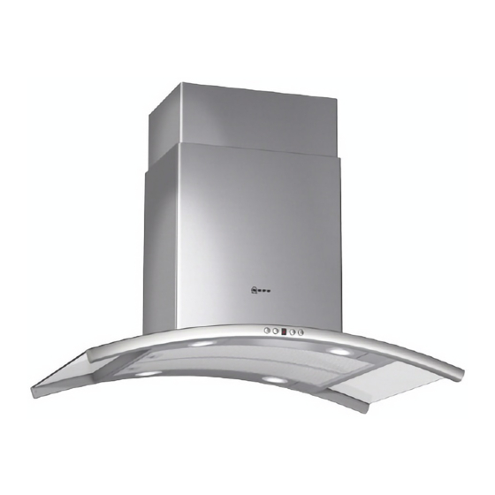
Page 3: Appliance Description
If the air intake is inadequate, there is a risk of poisoning from combustion gases Light / fan Filter grille which are drawn back into the room. -
Page 4: Before Using For The First Time
Use carefully. They contain important you may find descriptions of individual information concerning your personal features that do not apply to your safety as well as on use and care of the specific appliance. appliance. This extractor hood complies with all Please retain the operating and relevant safety regulations. -
Page 5: Operating Procedure
By cleaning the metal grease filters at appropriate intervals, the possibility of them Setting the required fan speed: catching fire as a result of a build-up of heat Press the + button. such as occurs when deep-fat frying or The fan speed is increased by one step. - Page 6 Removing the filter: Warning: The halogen bulbs must be switched off and cool. 1. Remove the metal filters. 2. Press the catches at both sides of the filter inwards and lift the carbon filter down and out. 2. Clean the filters.
-
Page 7: Cleaning And Care
1. Switch off the extractor hood and pull electricity supply by pulling out the out the mains plug or switch off the mains plug or switching it off at the fuse electricity supply at the fuse box. box. When switched on, the halogen bulbs At the same time as you clean the become very hot. -
Page 8: Installation Instructions
Only one side of the extractor hood Please ask your dealer or inquire at your may be installed next to a high-sided unit local authority about current means of or high wall. Gap at least 50 mm. -
Page 9: Prior To Installation
flue that is interlocking, etc. currently used for other purposes, nor into a shaft that is used for ventilating rooms in If the air intake is inadequate, there is a which stoves or fireplaces are also located. - Page 10 Short, smooth air exhaust pipe. Mount the pipe directly onto the air As few bends in the pipe as possible. outlet on the hood. Diameter of pipe to be as large as possible and no tight bends in pipe.
-
Page 11: Electrical Connection
A separator must be installed in the house- hold circuit. A suitable separator is a switch that has a contact gap of more than 3 mm and interrupts all poles. Such devices include circuit breakers and contactors. -
Page 12: Installation
Exhaust air 430 - 710 2. Using the template, mark screw Circulating air positions on the ceiling. 430 - 750 3. Drill 4x 8 mm holes and insert wall plugs flush with the ceiling. min. 550 electric 650 gas... - Page 13 8 screws. Exhaust air 430 – 710 Circulating air 430 – 750 09. Screw the extractor hood to the support frame and screw back the panel. 6. Screw the support frame to the ceiling with 4 screws. 7. Remove the panel.
- Page 14 11. Connect the pipes. screw into position. 12. Connect the power. 13. Carefully remove the protective foil. 14. Place the two sections of the upper flue on the extractor hood and clip together. Protect the extractor hood from damage. 16. Insert the two sections of the lower flue and clip together.
- Page 15 Accessories: Z5120X5 351210...
- Page 16 NEFF (UK) Ltd. Grand Union House, Old Wolverton Road, Old Wolverton Milton Keynes, MK12 5PT Tel: 01908 328300 9000 032 329 Fax: 01908 328399 Printed in Germany 0105 Es.
Need help?
Do you have a question about the I89D55N0GB and is the answer not in the manual?
Questions and answers