Advertisement
Quick Links
Advertisement

Subscribe to Our Youtube Channel
Related Manuals for Circuitmess Sparkly


Summary of Contents for Circuitmess Sparkly
- Page 1 CREATOR’S BOOKLET...
- Page 2 Enhance your STEM knowledge with the CircuitMess toy collection! Wacky Robots are a quirky group of mini-robots that will help you master the basics of robotics and electronics. Collect all the Wacky Robots and unlock new games for the BIT!
- Page 3 Connect your robots to Sparkly, a robot car that follows the source of light. Sparkly, BIT, and Wacky Robots are sold separately.
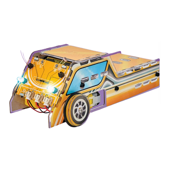
- Page 4 Meet CircuitMess Sparkly Introducing Sparkly, your new robot car that will introduce you to the exciting world of robotics and STEM. Sparkly teaches you about different electronic components and how photoresistors work. Finally, you’ll have a cool car for transporting your...
- Page 5 What is CircuitMess? Albert CircuitMess started in 2016 when Albert (our CEO) was 17. Albert loved tinkering with electronics, and one of his first projects was a DIY game console. People liked the idea, so he launched it on Kickstarter,...
- Page 6 The mission Everybody knows how important technology is, but less than 1% of the population knows HOW TO MAKE new technology. We’re here to change that! With our kits, we want to inspire people to be CREATORS instead of just consumers.
- Page 8 What’s inside the box? Stickers Photoresistors Acrylic casings Small metal screws Large plastic bolts AA batteries Battery holder Electromotors LEDs Metal ball caster wheel Small plastic standoffs Large standoffs Small plastic bolts Wheels Big metal screws You’ll learn about: Electronics and different Photoresistors Photoresistance electronic components...
- Page 10 When light falls on the photoresistor, its resistance decreases, allowing current to flow. Sparkly has two photoresistors that help it detect the source of light and adjust its movements accordingly.
- Page 11 Photoresistors The photoresistor was invented by American engineer and inventor Joseph John Lister, and the product was patented in 1930. The first photoresistor was used on a vacuum tube to measure the strength of radio signals shown on a fluorescent screen. The idea was to help users improve their radio reception.
- Page 12 Potentiometer In 1872, Thomas Edison invented the first potentiometer. potentiometer is a manually adjustable resistor with 3 terminals. Two terminals are connected to opposite ends of the resistive element, while the third is connected to a sliding contact called the wiper, which slides across the resistive element.
- Page 13 Potentiometers take an input voltage and transmit varying amounts into an electrical circuit. The position of the wiper determines this amount. Input voltage Sliding contact Output voltage Different types of potentiometers: MOTORISED SLIDE POTENTIOMETER SLIDE POTENTIOMETER MULTI-TURN STACKED POTENTIOMETER POTENTIOMETER...
- Page 15 Keep CircuitMess Sparkly away from young children! This product contains small components that are dangerous to children under the age of 3. If you are a minor, assemble Sparkly strictly with the help of an adult. Closely follow all the instructions you received in this kit and those found on our online pages so that no one gets hurt.
- Page 16 Sparkly Build Guide ACRYLIC CASINGS You’ll need to break one large acrylic piece from the kit to get a bunch of smaller casings. Warning: Be careful when breaking to avoid damaging the parts you need. In the end, you should have eight separate pieces of acrylic casings.
- Page 17 Remove the protective foil from both sides of the casings now:...
- Page 18 After removing the foil, the casings should be transparent. Now it’s time for Sparkly to get a fun look! Grab the stickers, and let’s begin.
- Page 19 Check that each part is stuck to the correct side. Your acrylic casings should look like this in the end: We’ve prepared two designs for the wheels for you to select from.
- Page 20 ASSEMBLY We may now begin the assembly. Firstly, take the PCB and both electromotors. Electromotors Markings (the letters L and R) indicate where the electromotors must be connected. Connect the motors like this:...
- Page 21 Turn the board around, cross the motor wires, and rotate the motors in the opposite direction of the board. This part will be important for later assembly.
- Page 22 The next step is to connect the batteries to the board and test whether the motors are moving in the right direction. We’ll need a battery holder, two small metal screws, two small plastic standoffs, and three AA batteries for this. Acrylic casing Battery...
- Page 23 We will attach the acrylic casing from the photo below to the back side of the holder so that the holes on the casing match the holes on the holder. Take the standoffs and fasten the holder and casing using them.
- Page 24 It’s time to put the batteries in. During this step, pay attention to the battery polarity (+ and -). Both on the battery and on the holder, it’s indicated which way the batteries should be positioned.
- Page 25 Plug in the connector from the holder into the PCB. The slot is located next to the motors and marked with a battery icon. Right motor switch Left motor switch on/off switch Turn on both motors by using the switches labeled L and R. If they are correctly positioned, both motors should rotate in the same direction.
- Page 26 Acrylic casing Driving ball Plastic Plastic bolts standoffs Put the casing on the bottom of the ball and put the bolts through the plastic part of the ball and the casing.
- Page 27 We’ll use the standoffs to fasten it on the backside. Repeat the step for the remaining bolt and standoff.
- Page 28 Set this aside and take the following components: Casing for Sparkly’s front Plastic Large bolts standoffs Plastic standoffs Place one of the bolts here:...
- Page 29 Fasten it with the smaller standoff from the inside.
- Page 30 Then, add the large standoff on top of it.
- Page 31 Repeat the step two more times as shown in the photo: Take the part with the PCB and electromotors and connect one of the motors to the casing like this. Be careful not to change the motor’s position.
- Page 32 Put one of the large plastic bolts through the casing and one of the holes in the motor.
- Page 33 You’ll fasten the bolt with the standoff. Then, repeat the step with another large bolt and standoff. This is what the motor should look like:...
- Page 34 Connect the PCB and the casing like this:...
- Page 35 Connect the motor to the second acrylic casing that represents one side of the car in the same way. Sparkly should now look like this: On the bottom, add the part with the ball. Make sure the ball is facing the floor.
- Page 36 We’ll need a screwdriver for this step. We can proceed if everything is connected.
- Page 37 We need to add wheels to Sparkly in order for him to move. Take the assembled part, wheels, two circle-shaped casings and two large metal screws. Circle-shaped Circle-shaped Wheels casing casing Metal screws The inside of the wheels has a slot that matches the extension on the motor where it needs to be put.
- Page 38 Check if the wheel is coming off from the motor. Then, take the casing and metal screw and put the metal screw through the casing and the wheel.
- Page 39 You’ll need a screwdriver to put the screw through the casing and wheel. Repeat this step for the other wheel.
- Page 40 The casing with the carved slots is placed on top of your Sparkly. You’ll put your Wacky Robots in this casing so they can drive on Sparkly.
- Page 41 The casing with Sparkly written on it is the roof, and you have to put it here: Take the photoresistors and the LEDs you want to put on your Sparkly. LEDs Photoresistors...
- Page 42 It makes no difference which way the photoresistors are oriented. They are used so that Sparkly can follow the light in the dark. When placing the LEDs, you need to pay attention to the polarity. The plus and minus signs indicate the LED’s rounded (+) and cut-off (-) parts.
- Page 43 You’ll use these potentiometers to decrease or increase the sensitivity of photoresistors in order to adjust Sparkly’s sensitivity depending on the lighting in the room. You can turn the potentiometers using the screwdriver. Potentiometers Place your Wacky Robots on Sparkly,...
- Page 44 CircuitMess Sparkly contains sensitive and dispose of it properly. electronic components. CircuitMess Sparkly or its components may be • If you are not sure whether your device damaged if dropped, burned, punctured, or the included battery is safe to use, crushed, or in contact with liquid.
- Page 45 (such as dust or metal powder), can be dangerous. The individual parts and components in the CircuitMess Sparkly can pose a Exposure of CircuitMess Sparkly to choking risk to children under 36 months. environments with high concentrations...
- Page 46 5. Teach children to always store the environment or human health from CircuitMess Sparkly and other parts of uncontrolled waste disposal, recycle the the CircuitMess Sparkly educational product responsibly. Recycling promotes kit appropriately to prevent accidents. the sustainable reuse of resources. For...
- Page 47 • If the defect is not remedied within a caused by improper packaging. reasonable period after receiving the product for repair, CircuitMess d.o.o. The rights under this warranty are will replace it with a new product. the exclusive and final rights of the customer unless otherwise •...
- Page 48 WARRANTY SHEET CircuitMess do-it-yourself Product name: educational set for electronics Warranty on components and 24 months parts contained in this set is: Date of purchase: Seller and point of sale stamp: Invoice number: Information on interventions during warranty period is entered by a repair shop technician at an authorized repair shop.
- Page 52 Scan QR code and find more fun games and lessons!
Need help?
Do you have a question about the Sparkly and is the answer not in the manual?
Questions and answers