
Related Manuals for Makita DLS713Z


Summary of Contents for Makita DLS713Z
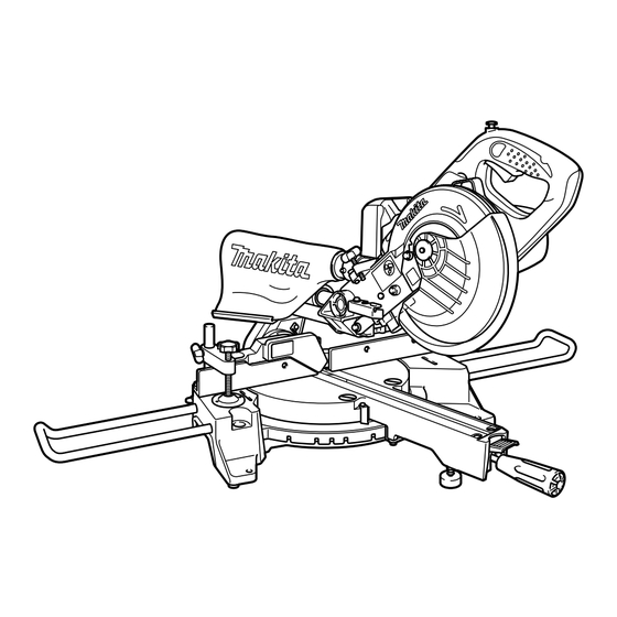
- Page 1 INSTRUCTION MANUAL Cordless Slide Compound Miter Saw DLS713 015247 IMPORTANT: Read Before Using.
-
Page 2: Specifications
ENGLISH (Original instructions) SPECIFICATIONS Model DLS713 Blade diameter 190 mm Blade body thickness 1.3 mm - 2.0 mm Hole (arbor) diameter 20 mm Max. Miter angle Left 47°, Right 57° Max. Bevel angle Left 45°, Right 5° Max. Cutting capacities (H x W) with blade 190 mm in diameter. Bevel angle Miter angle 45°... -
Page 3: Ec Declaration Of Conformity
000331 Sound power level (L ) : 98 dB (A) Yasushi Fukaya Uncertainty (K) : 3 dB (A) Director Makita, Jan-Baptist Vinkstraat 2, 3070, Belgium Wear ear protection GEA006-2 ENG900-1 Vibration General Power Tool Safety Warnings The vibration total value (tri-axial vector sum) determined... - Page 4 If operating a power tool in a damp location is 20. Store idle power tools out of the reach of unavoidable, use a ground fault circuit children and do not allow persons unfamiliar interrupter (GFCI) protected supply. Use of an with the power tool or these instructions to GFCI reduces the risk of electric shock.
- Page 5 ENB118-4 21. Support long workpieces with appropriate additional supports. CORDLESS MITER SAW SAFETY 22. Never cut so small workpiece which cannot be WARNINGS securely held by the vise. Improperly held workpiece may cause kickback and serious Keep hands out of path of saw blade. Avoid personal injury.
-
Page 6: Installation
42. Always use accessories recommended in this Do not expose battery cartridge to water manual. Use of improper accessories such as or rain. abrasive wheels may cause an injury. A battery short can cause a large current flow, 43. Take care when slotting. overheating, possible burns and even a breakdown. -
Page 7: Functional Description
FUNCTIONAL DESCRIPTION 1. Bolt WARNING: Always be sure that the tool is switched off and • battery cartridge is removed before adjusting or checking the functions on the tool. Failure to switch off and remove the battery cartridge may result in serious personal injury from 011236 accidental start-up. -
Page 8: Blade Guard
Overloaded: For European countries • The tool is operated in a manner that causes 1. Blade guard A it to draw an abnormally high current. 2. Blade guard B In this situation, release the trigger switch on the tool and stop the application that caused the tool to become overloaded. - Page 9 Do not remove spring holding blade guard. If 2. Guide fence guard becomes damaged through age or UV light 3. Turn base exposure, contact a Makita service center for a new guard. DO NOT DEFEAT OR REMOVE GUARD. Positioning kerf board 1. Thumb screw 2.
- Page 10 NOTICE: Stopper arm When turning the turn base, be sure to raise the • handle fully. 1. Adjusting screw 2. Stopper arm Adjusting the bevel angle 1. Lever 2. Release button 011241 The lower limit position of the blade can be easily adjusted with the stopper arm.
-
Page 11: Switch Action
A hole is provided in the switch trigger for insertion of a in unintentional operation and serious personal padlock to lock the tool off. injury. Return tool to a Makita service center for proper repairs BEFORE further usage. NEVER defeat the lock-off button by taping down or •... - Page 12 Accidental start up of the tool may result in serious personal injury. 012719 CAUTION: Use only the Makita hex wrench provided to install • 1. Blade case or remove the blade. Failure to do so may result in 2.
-
Page 13: Securing Workpiece
outer flange and hex socket bolt, and then use the hex wrench 1. Support to tighten the hex socket bolt (left-handed) securely 2. Turn base counterclockwise while pressing the shaft lock. Return the blade guard and center cover to its original position. -
Page 14: Operation
Horizontal vise (optional accessory) 1. Holder assembly 1. Vise knob 2. Rod 12 2. Projection 3. Vise shaft 4. Base 002246 WARNING: 011305 The horizontal vise can be installed on the left side of the Always support a long workpiece so it is level •... - Page 15 Workpieces up to 52 mm high and 97 mm wide can Never perform the slide cut with the handle locked • be cut in the following manner. in the lowered position. Push the carriage toward the guide fence fully and Never loosen the knob which secures the carriage •...
- Page 16 NOTICE: 1. Inside corner When pressing down the handle, apply pressure in • 2. Outside corner parallel with the blade. If a force is applied perpendicularly to the turn base or if the pressure direction is changed during a cut, the precision of the cut will be impaired.
- Page 17 Lay crown molding with its broad back • (hidden) surface down on the turn base Over 15mm (5/8") Over 420mm (16-1/2") with its CEILING CONTACT EDGE against the guide fence on the saw. 50mm-60mm 35mm (2"-2-3/8") The finished piece to be used will (1-3/8") •...
-
Page 18: Carrying Tool
Make sure that the battery cartridge is removed. Secure Groove cutting the blade at 0° bevel angle and the turn base at the full right miter angle position. Secure the slide poles so that 1. Cut grooves with the lower slide pole is locked in the position of the carriage blade fully pulled to operator and the upper poles are locked in the position of the carriage fully pushed forward to the... - Page 19 1. Guide fence 1. Lever 2. Hex socket bolt 2. Arm holder 3. 0 degree bevel angle adjusting bolt 4. Arm 5. Release button 015252 012589 Loosen the hex socket bolt securing the guide Loosen the lever at the rear of the tool. fence using the hex wrench.
-
Page 20: Optional Accessories
Misuse of an accessory or Replacing carbon brushes attachment may result in serious personal injury. If you need any assistance for more details regarding 1. Limit mark these accessories, ask your local Makita Service Center. Carbide-tipped saw blades • Vise assembly (Horizontal vise) •... - Page 24 Makita Jan-Baptist Vinkstraat 2, 3070, Belgium Makita Corporation Anjo, Aichi, Japan www.makita.com 885295A220...
Need help?
Do you have a question about the DLS713Z and is the answer not in the manual?
Questions and answers