Advertisement
Special-purpose Basic Switch
DZ
DPDT Basic Switch for Two Independent
Circuit Control
• Incorporates two completely independent built-in switches.
• Ideal for switching the circuits operating on two different voltag-
es, and for controlling two independent circuits.
• Interchangeable with OMRON Z Basic Switches, as both
switches are identical in mounting hole dimensions, mounting
pitch and pin plunger position.
Model Number Structure
■ Model Number Legend
DZ-10G@-1@
1 2 3 4 5
1. Ratings
10:
10 A (250 VAC)
2. Contact Gap
G:
0.5 mm
3. Actuator
None: Pin plunger
V:
Hinge lever
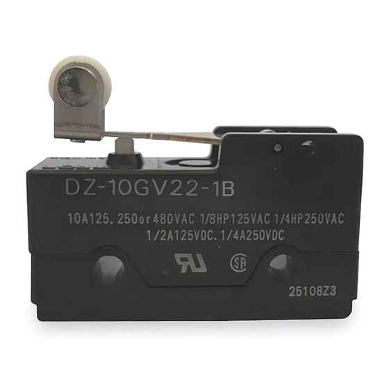
V22: Short hinge roller lever
V2:
Hinge roller lever
W:
Hinge lever
W22: Short hinge roller lever
W2:
Hinge roller lever
Ordering Information
■ List of Models
Actuator
Pin plunger
Hinge lever
Short hinge roller lever
Hinge roller lever
4. Contact Form
1:
DPDT
5. Terminals
A:
Solder terminal
B:
Screw terminal
OT
Solder terminal
0.13 mm min.
DZ-10G-1A
1.6 mm min.
DZ-10GW-1A
0.4 mm min.
DZ-10GV-1A
0.9 mm min.
DZ-10GW22-1A
0.13 mm min.
DZ-10GV22-1A
1.2 mm min.
DZ-10GW2-1A
0.26 mm min.
DZ-10GV2-1A
Screw terminal
DZ-10G-1B
DZ-10GW-1B
DZ-10GV-1B
DZ-10GW22-1B
DZ-10GV22-1B
DZ-10GW2-1B
DZ-10GV2-1B
Special-purpose Basic Switch
DZ
F-139
Advertisement
Table of Contents

Subscribe to Our Youtube Channel
Related Manuals for Omron DZ


Summary of Contents for Omron DZ
-
Page 1: Ordering Information
DPDT Basic Switch for Two Independent Circuit Control • Incorporates two completely independent built-in switches. • Ideal for switching the circuits operating on two different voltag- es, and for controlling two independent circuits. • Interchangeable with OMRON Z Basic Switches, as both switches are identical in mounting hole dimensions, mounting pitch and pin plunger position. -
Page 2: Specifications
0.03 A 0.03 A Note: 1. Inductive load has a power factor of 0.4 min. (AC) and a time constant of 7 ms max. (DC). 2. Lamp load has an inrush current of 10 times the steady-state current. 3. Motor load has an inrush current of 6 times the steady-state current. -
Page 3: Engineering Data
2. Unless otherwise specified, a tolerance of 0.4 mm applies to all dimensions. 3. The solder terminal model has a suffix “-1A” in its model number and its omitted dimensions are the same as the corresponding dimen- sions of the pin plunger model. - Page 4 Short Hinge Roller Lever OF max. 3.92 N {400 gf} RF min. 0.83 N {85 gf} DZ-10GW22-1B t = 1 (stainless-steel lever) OT min. 0.9 mm 28.4 9.5 dia. 4 (plastic roller) MD max. 2.4 mm 26.2R FP max. 39.7 mm 30.2 0.8 mm...
-
Page 5: Terminal Connection
Use M4 mounting screws with plane washers or spring washers to of the soldering iron is 60 W maximum. Do not take more than 5 s to securely mount the Switch. Tighten the screws to a torque of 1.18 to solder any part of the Switch. - Page 6 ALL DIMENSIONS SHOWN ARE IN MILLIMETERS. To convert millimeters into inches, multiply by 0.03937. To convert grams into ounces, multiply by 0.03527. In the interest of product improvement, specifications are subject to change without notice. Cat. No. B060-E1-07 F-144 Special-purpose Basic Switch...
Need help?
Do you have a question about the DZ and is the answer not in the manual?
Questions and answers