
Subscribe to Our Youtube Channel
Related Manuals for Safe Fleet RVS AIR VUE AV-L17


Summary of Contents for Safe Fleet RVS AIR VUE AV-L17
- Page 1 2.4GHz 7” Digital Wireless TFT LCD Monitor AV-L17 Instruction Manual © Rear View Safety 2024...
-
Page 2: Table Of Contents
TABLE OF CONTENTS Introduction..................3 Safety Information ..................4 Precautions ....................7 1. Maintenance .....................7 2. Features .....................3 3. Technical Specifications ................9 4. Accessories ...................10 5. Parts Identification ..................11 6. Remote Control Operation ..............12 7. Basic Operation ..................13 8. Connection diagram ................14 9. Menu Operation and Functional Specification .........15 9.1 Preview Interface ..................15 9.2 Main Menu ....................16 10. -
Page 3: Introduction
INTRODUCTION Congratulations on purchasing an Air Vue Digital Wireless Monitor! With this manual, you can properly install and operate the unit. The wireless monitor is intended to be installed as a supplemental aid to the standard rear- view mirror that already exists in your vehicle. The monitor should not be used as a substitute for your vehicle's standard rear-view mirror or any other mirror. -
Page 4: Safety Information
SAFETY INFORMATION PLEASE READ THE ENTIRE MANUAL AND FOLLOW THE INSTRUCTIONS AND WARNINGS CAREFULLY. FAILURE TO DO SO CAN CAUSE SERIOUS DAMAGE AND/OR INJURY, INCLUDING LOSS OF LIFE. BE SURE TO OBEY ALL APPLICABLE LOCAL TRAFFIC AND MOTOR VEHICLE REGULATIONS AS IT PERTAINS TO THIS PRODUCT. - Page 5 SAFETY INFORMATION INSTALLATION Electric shock or product malfunction may occur if this product is installed incorrectly. Use this product within the voltage range specified. Failure to do so can • cause electronic shock or product malfunction. Take special care when cleaning the monitor. •...
- Page 6 If you have questions about this product, please contact us at: 800.764.1028 sales@rearviewsafety.com www.rearviewsafety.com New York 1797 Atlantic Ave Brooklyn, NY 11233 Indiana 319 Roske Dr. Elkhart, Indiana 46516 Canada 68 Trafalgar Square Thornhill, ON, L4J 7M5, Canada IN NO EVENT SHALL SELLER OR MANUFACTURER BE LIABLE FOR ANY DIRECT OR CONSEQUENTIAL DAMAGES OF ANY NATURE, OR LOSSES OR EXPENSES RESULTING FROM ANY DEFECTIVE PRODUCT OR THE USE OF ANY PRODUCT.
-
Page 7: Precautions
PRECAUTIONS 1. Do not expose the monitor to excessive heat or coldness. Storage temperature is -30~+80°C; Operating temperature is -20~+70°C; with a maximum relative humidity of 90%. 2. Never use this device near a bathtub, wash basin, kitchen, damp basement, swimming pool or similar places. -
Page 8: Maintenance
1. MAINTENANCE Remove all the cable connections from the monitor before cleaning the device. Use a mild household detergent and clean the unit with a slightly damp, soft cloth. Never use strong solvents such as thinner or benzine, as they might damage the finish of the device. -
Page 9: Features
2. PRODUCT FEATURES TFT LCD monitor with wide angle view and high-resolution display Image can be set to horizontally flipped, vertically flipped and normal Support backlight adjustment manually and automatically 1.5W speaker Monitor operated by remote control or physical buttons on display Working voltage: 10-32V Compliance with CE/FCC standards Pairing through PLC communication... -
Page 10: Accessories
4. ACCESSORIES SPECIAL NOTICE: Accessory supply may be different for different application. Rear View Safety, 1797 Atlantic Ave., Brooklyn NY 11233 800.764.1028 sales@rearviewsafety.com www.rearviewsafety.com... -
Page 11: Parts Identification
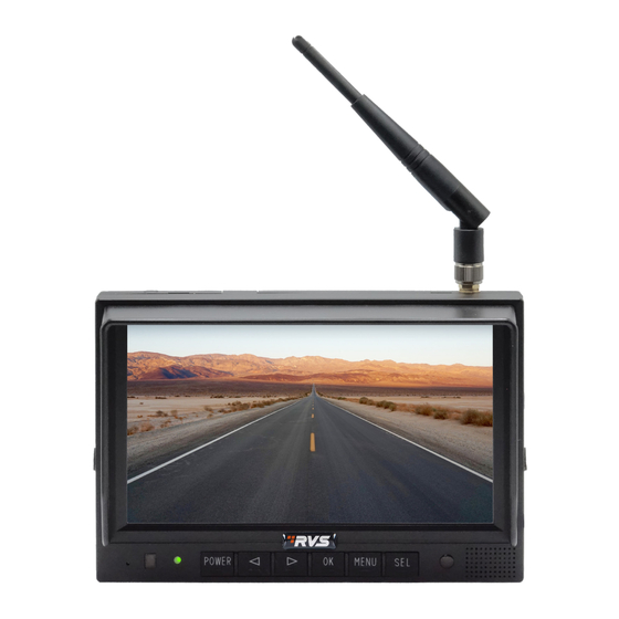
5. PARTS IDENTIFICATION Digital Color LCD Screen Power Indicator Remote Control Sensor Menu Light Sensor Select Channels Loudspeaker Power Switch Press OK button to enter menu item. Volume Up Press OK button shortcut for start/stop recording. Volume Down Micro SD Card Slot Mounting Bracket Rear View Safety, 1797 Atlantic Ave., Brooklyn NY 11233 800.764.1028 sales@rearviewsafety.com... -
Page 12: Remote Control Operation
6. REMOTE CONTROL OPERATION Press to turn on/off Press to select MUTE or enable sound the monitor Press OK button to enter Press to show menu menu item. Press OK or exit menu button - shortcut for start/stop recording Volume increase and menu selection right Volume decrease and MIR-Flip selection... -
Page 13: Basic Operation
7. BASIC OPERATION 7.1. Installation of Center Mounting Bracket 1. Adjust monitor level by sliding the support to the desired height. 2. Adjust the angle of the monitor and tighten the knob on the center mounting bracket. Support Attaching Piece Knob 7.2. -
Page 14: Connection Diagram
8. CONNECTION DIAGRAM Red wire to positive power supply of DC/10-32V. Black wire to Ground. Connect the transmitter and display monitor to the same DC power circuit to achieve reliable pairing. Rear View Safety, 1797 Atlantic Ave., Brooklyn NY 11233 800.764.1028 sales@rearviewsafety.com www.rearviewsafety.com... -
Page 15: Menu Operation And Functional Specification
9. MENU OPERATION AND FUNCTIONAL SPECIFICATION 9.1 Preview Interface Under the main page, press the menu button on the monitor or infrared remote control or click (touch operation is disabled by default) in the red frame area to call out the main menu If the Pair Request sent by the Transmitter has not been received for 2s in a row, the following picture will... -
Page 16: Main Menu
If 2.4GHz signal is lost, the monitor will display NO SIGNAL and quickly re-enter the pairing state. 9.2 Main Menu Click the corresponding icon (or select the corresponding icon and press the OK button on the display or infrared remote control) to enter the selected function interface. Click the part outside the red box (or press the MENU button on the display or infrared remote control) to Exit the menu selection interface, long press the POWER button on the display to turn on/off the touch screen operation... - Page 17 1. Camera Brightness: Drag the corresponding slider bar to adjust the brightness. Contrast: Drag the corresponding slider bar to adjust the contrast. Saturation: Drag the corresponding slider bar to adjust the saturation. Hue: Drag the corresponding slider bar to adjust the hue. Volume: Drag the corresponding slider bar to adjust the volume.
- Page 18 2. Record Record Time: choose the duration of the video Format SD Card: “SD Card Format?” will pop up, press Yes to format the SD card. Power On Record: If it is set to on, the monitor will start recording video upon startup. This function is set on by default.
- Page 19 3. Playback Video: The folder will increase with video files automatically. A new folder will be created once the files exceed a maximum of 997 in a folder. The larger the folder number, the newer folder. If the SD card is full, files will be deleted from the oldest folder Camera: Indicates the camera that performed the recording.
-
Page 20: Installation Tips
4. Date and Time Touch or press left/right plus OK key of the remote control to enter the value setting interface, and set the date and time through the small keyboard. Date: Select the corresponding year, month and day Time: Select the corresponding hour, minute, and second 10. -
Page 21: Wireless System Installation Instruction
10.1 WIRELESS SYSTEM INSTALLATION INSTRUCTION. The monitor needs to be connected to the same circuit as the wireless transmitter device. This is most likely the Trailer ABS circuit (note: there may be several Trailer ABS circuits). Safely and securely using appropriate and approved methods, connect the red positive voltage power harness wire to this circuit. -
Page 22: Troubleshooting
11. TROUBLESHOOTING Solutions for Poor Transmitter Signal Please confirm the antennas of the display and on the transmitter are perpendicular to the ground, and the antennas are tightened. If there is metal shielding between the monitor and the camera, an extended antenna should be used to bypass the metal shielding to ensure smooth transmission of antenna signal in space. -
Page 23: Warranty
ONE YEAR WARRANTY REAR VIEW SAFETY, INC. WARRANTS THIS PRODUCT AGAINST MATERIAL DEFECTS FOR A PERIOD OF ONE YEAR FROM DATE OF PURCHASE. WE RESERVE THE RIGHT TO REPAIR OR REPLACE ANY SUCH DEFECTIVE UNIT AT OUR SOLE DISCRETION. REAR VIEW SAFETY, INC. IS NOT RESPONSIBLE FOR A DEFECT IN THE SYSTEM AS A RESULT OF MISUSE, IMPROPER INSTALLATION, DAMAGE OR MISHANDLING OF THE ELECTRONIC COMPONENTS. -
Page 24: Disclaimer
DISCLAIMER REAR VIEW SAFETY AND/OR ITS AFFILIATES DOES NOT GUARANTEE OR PROMISE THAT THE USER OF OUR SYSTEMS WILL NOT BE IN/PART OF AN ACCIDENT OR OTHERWISE NOT COLLIDE WITH AN OBJECT AND/OR PERSON. OUR SYSTEMS ARE NOT A SUBSTITUTE FOR CAREFUL AND CAUTIOUS DRIVING OR FOR THE CONSISTENT ADHERENCE TO ALL APPLICABLE TRAFFIC LAWS AND MOTOR VEHICLE SAFETY REGULATIONS. - Page 25 Rear View Safety, 1797 Atlantic Ave., Brooklyn NY 11233 800.764.1028 sales@rearviewsafety.com www.rearviewsafety.com...
- Page 26 Rear View Safety, 1797 Atlantic Ave., Brooklyn NY 11233 800.764.1028 sales@rearviewsafety.com www.rearviewsafety.com...
- Page 27 Rear View Safety, 1797 Atlantic Ave., Brooklyn NY 11233 800.764.1028 sales@rearviewsafety.com www.rearviewsafety.com...
- Page 28 Engineered For Vehicle Safety If you have questions about this product, please contact us at: 800.764.1028 sales@rearviewsafety.com www.rearviewsafety.com New York 1797 Atlantic Ave Brooklyn, NY 11233 Indiana 319 Roske Dr. Elkhart, Indiana 46516 Canada 68 Trafalgar Square Thornhill, ON, L4J 7M5, Canada...
Need help?
Do you have a question about the RVS AIR VUE AV-L17 and is the answer not in the manual?
Questions and answers