
Related Manuals for GORMAN-RUPP PUMPS SFDV4A


Summary of Contents for GORMAN-RUPP PUMPS SFDV4A
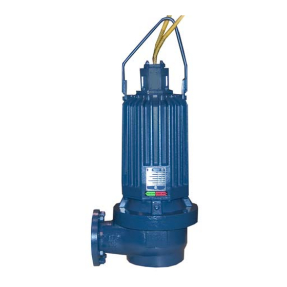
- Page 1 OM-06406-02 August 23, 2022 INSTALLATION, OPERATION, AND MAINTENANCE MANUAL WITH PARTS LIST DRY PIT SUBMERSIBLE PUMP MODEL SFDV4A & SFDEV4A GORMAN‐RUPP PUMPS www.grpumps.com 2022 Gorman‐Rupp Pumps Printed in U.S.A.
- Page 2 Register your new Gorman‐Rupp pump online at www.grpumps.com Valid serial number and e‐mail address required. RECORD YOUR PUMP MODEL AND SERIAL NUMBER Please record your pump model and serial number in the spaces provided below. Your Gorman‐Rupp distributor needs this information when you require parts or service. Pump Model: Serial Number:...
-
Page 3: Table Of Contents
TABLE OF CONTENTS INTRODUCTION ..........PAGE I - 1 SAFETY ‐... - Page 4 TABLE OF CONTENTS (continued) PARTS LISTS: Pump Model Assembly ..........PAGE E - 3 Motor Assemblies .
-
Page 5: Introduction
SF SERIES OM-06406 INTRODUCTION Thank You for purchasing a Gorman‐Rupp pump. HAZARD AND INSTRUCTION Read this manual carefully to learn how to safely DEFINITIONS install and operate your pump. Failure to do so could result in personal injury or damage to the The following are used to alert maintenance per... -
Page 6: Safety - Section A
SF SERIES OM-06406 SAFETY - SECTION A This information applies to the SF Se ries submersible pump indicated on the front cover of this manual. The electrical power used to operate In addition to this manual, see the sepa this pump is high enough to cause inju rate literature covering the control box, ry or death. - Page 7 OM-06406 SF SERIES to the incoming power lines. The pump electrical ground. Be sure that the in motor is designed to operate through a coming power matches the voltage and Gorman‐Rupp approved control box phase of the pump and control before which provides overload protection and connecting the power source.
- Page 8 SF SERIES OM-06406 approved by the manufacturer, can re sult in severe injury or death and void warranty. Do not remove plates, covers, gauges, pipe plugs, or fittings from an over heated pump. Vapor pressure within the pump can cause parts being disen After the pump has been installed, make gaged to be ejected with great force.
-
Page 9: Installation - Section B
SF SERIES OM-06406 INSTALLATION - SECTION B Review all SAFETY information in Section A. PUMP SEALS Since pump installations are seldom identical, this This pump is equipped with two mechanical seals. section is intended only to summarize general rec The lower seal is lubricated by the liquid being ommendations and practices required to inspect, pumped and prevents the liquid from entering the position, and arrange the pump and piping. -
Page 10: Lifting
OM-06406 SF SERIES TABLE B-1. PUMP MOTOR SPECIFICATIONS MODEL VOLTAGE/ SIZE H.P . MOTOR LOCKED PHASE LOAD ROTOR AMPS AMPS SFDV4A, SFDEV4A 208/3 4” 1750 13.80 106.1 SFDV4A, SFDEV4A 230‐460‐575/3 4” 1750 13.0/6.5/5.2 96.0/48.0/38.4 Lifting Piping NOTE Pump unit weights will vary depending on the Refer to Pump Performance in OPERATION - mounting and drive provided. -
Page 11: Field Wiring Connections (Incoming Power)
SF SERIES OM-06406 or death to personnel can result from Motor Cable Grounding Test any alteration to the cable. Field Wiring Connections (Incoming Power) Do not connect the pump power or con Field wiring is not provided with this pump, and trol cables to the control box or incom... -
Page 12: Liquid Level Devices
OM-06406 SF SERIES Refer to Figure B-1 and connect the pump motor desirable, connect only to controls which cable to the control box. are wired for manual restart. Refer to the appropriate wiring diagram accompa nying the control box when making electrical con nections. - Page 13 SF SERIES OM-06406 PUMP PUMP CONTROL BOX CONTROL BOX TO LEVEL CONTROL CIRCUIT TO LEVEL CONTROL CIRCUIT IN MAIN CONTROL IN MAIN CONTROL LIQUID LEVEL LIQUID LEVEL RANGE RANGE DEWATERING DEWATERING ON (FILLING) ON (FILLING) BULB (FLOAT TYPE) DIAPHRAGM TYPE Figure B-3.
-
Page 14: Operation - Section C
SF SERIES OM-06406 OPERATION - SECTION C GENERAL INFORMATION pendent upon the quality and performance of the electrical controls, the pump warran Review all SAFETY information in Section A. ty is valid only when controls have been specified or provided by The Gorman‐ Rupp Company. - Page 15 OM-06406 SF SERIES SFDV4A 230/460/575V 3P PERFORMANCE CURVE PAGE C - 2 OPERATION...
- Page 16 SF SERIES OM-06406 SFDV4A 208V 3P PERFORMANCE CURVE OPERATION PAGE C - 3...
- Page 17 OM-06406 SF SERIES SFDEV4A 230/460/575V 3P PERFORMANCE CURVE PAGE C - 4 OPERATION...
- Page 18 SF SERIES OM-06406 SFDEV4A 208V 3P PERFORMANCE CURVE OPERATION PAGE C - 5...
-
Page 19: Control Box
OM-06406 SF SERIES Control Box 2. Lock out the power to the control panel to ensure that the pump will Control boxes are available as optional equipment remain inoperative. from the factory. The control boxes contain con 3. Allow the pump to completely cool trols for starting and stopping the pump, and pro... -
Page 20: Impeller Rotation
SF SERIES OM-06406 burns and injuries. If overheating of the ry or death. Make certain that incoming pump occurs: power is off and locked out before inter changing motor leads. 1. Stop the pump immediately. 2. Ventilate the area. 3. Allow the pump to completely cool. 4. - Page 21 OM-06406 SF SERIES between starts, it will over‐heat, resulting in check for unusual noises or excessive vi damage to the motor windings. bration while the pump is running. If noise or vibration is excessive, stop operation Stopping and refer to the troubleshooting chart in the maintenance and repair manual.
-
Page 22: Cold Weather Preservation
SF SERIES OM-06406 COLD WEATHER PRESERVATION first two weeks of operation, and every month thereafter. Before installing or removing the lubrication plugs, always clean the area around the plugs to prevent contamination. Do not attempt to thaw the pump by us Draining Oil ing a torch or other source of flame. -
Page 23: Troubleshooting - Section D
SF SERIES OM-06406 TROUBLESHOOTING - SECTION D Review all SAFETY information in Section A. NOTE Many of the probable remedies listed in the TROU BLESHOOTING CHART require use of electrical test instruments; for specific procedures, see ELECTRICAL TESTING at the end of the chart. TROUBLESHOOTING CHART TROUBLE POSSIBLE CAUSE... - Page 24 OM-06406 SF SERIES TROUBLESHOOTING CHART (cont'd) TROUBLE POSSIBLE CAUSE PROBABLE REMEDY Discharge head too high. Reduce discharge head or install MOTOR RUNS, BUT staging adaptor and additional PUMP FAILS TO DELIVER RATED pump. DISCHARGE. Low or incorrect voltage. Measure control box voltage, both when pump is running and when shut off.
- Page 25 SF SERIES OM-06406 ELECTRICAL TESTING 3. The pump submerged and running under full load. Make the electrical checks which follow to deter The voltage measured under each condition mine if pump malfunctions are being caused by must be the same. problems in the motor or in the motor cable.
- Page 26 OM-06406 SF SERIES motor cable green/yellow ground lead. Touch and 1 megohm, insulation is acceptable but the other test lead to each of the motor cable should be rechecked regularly. If resistance leads in turn. Note the readings. reads less than 1 megohm, insulation should be checked more closely and frequently.
-
Page 27: Pump Maintenance And Repair - Section E
SF SERIES OM-06406 PUMP MAINTENANCE AND REPAIR - SECTION E GENERAL INFORMATION charge hoses and piping must be re moved from the pump before lifting. Lift the pump or component only as high as Review all SAFETY information in Section A. necessary and keep personnel away from suspended objects. - Page 28 OM-06406 SF SERIES ILLUSTRATION PARTS PAGE Figure E-1. SFDV4A & SFDEV4A Pump Model Assembly PAGE E - 2 MAINTENANCE AND REPAIR...
- Page 29 SF SERIES OM-06406 SFDV4A & SFDEV4A Pump Model Assembly Parts List (From S/N 1823170 Up) If your pump serial number is followed by an “N”, your pump is NOT a standard production model. Contact the Gorman‐Rupp Company to verify part numbers.
- Page 30 OM-06406 SF SERIES ILLUSTRATION Figure E-2. Motor Assemblies PAGE E - 4 MAINTENANCE AND REPAIR...
- Page 31 SF SERIES OM-06406 Motor Assemblies Parts List ITEM PART PART NAME NUMBER STATOR/HOUSING SUB-ASSEMBLY: -230V/1P 47113-118 --MOTOR HOUSING 38311-066 10000 --STATOR 47113-106 --TERMINAL HOUSING STUD MC1042 17000 --ROTATION DECAL 38815-027 -208‐230V/3P , 460V/3P 47113-119 --MOTOR HOUSING 38311-066 10000 --STATOR 47113-091 --TERMINAL HOUSING STUD MC1042 17000 --ROTATION DECAL...
- Page 32 OM-06406 SF SERIES Check the chart in TROUBLESHOOTING, Section PUMP AND SEAL DISASSEMBLY AND D of this manual, to determine the nature of the REASSEMBLY pump problem. If the problem is mechanical in na ture, such as worn pump parts, seal replacement, lubrication, etc., refer to PUMP END DISASSEM...
- Page 33 SF SERIES OM-06406 pump end components horizontally on a flat sur NOTE face for further disassembly. Chock the pump to When appropriate recycling facilities are available, prevent rolling when positioned horizontally. the user should recycle components and fluids when doing any routine maintenance / repairs and Remove the O‐ring (16) from the outer shoulder of also at the end of the pump’s useful life.
- Page 34 OM-06406 SF SERIES Remove the impeller washer (3). Remove the metal Remove the seal retaining ring (10) using snap ring rod from between the vanes of the impeller. pliers. Use caution when removing the retaining ring; tension on the seal spring will be released. To remove the impeller, use two thin‐bladed screw...
- Page 35 SF SERIES OM-06406 Thoroughly clean all reuseable parts with a soft Neither of the shaft seal assemblies should be re cloth soaked in cleaning solvent. Remove all O‐ used because wear patterns on the finished faces rings and clean the sealing surfaces. cannot be realigned during reassembly.
- Page 36 OM-06406 SF SERIES NOTE When pressing seal components onto the shaft, use hand pressure only. A push tube cut from a length of plastic pipe will aid in installing seal com The seal assemblies are not designed for ponents. The I.D. of the push tube should be ap operation at temperatures above 104_F proximately the same as the I.D.
- Page 37 SF SERIES OM-06406 the seal plate for the capscrews (17) with those in Impeller Installation the intermediate and slide the seal plate onto the (Figure E-1) shaft until fully seated against the intermediate. Be careful not to damage the stationary element al Inspect the impeller (2) for cracks, broken vanes, ready installed in the seal plate.
- Page 38 OM-06406 SF SERIES Use a suitable lifting device to reposition the pump Terminal Housing Assembly Removal in the wet well or sump. (Figure E-1) The terminal housing assembly (10) may be re MOTOR DISASSEMBLY placed without disassembling the motor or pump end components.
- Page 39 SF SERIES OM-06406 Stator Removal (Figure E-2) To prevent damage during removal from the shaft, it is recommended that bearings be cleaned and inspected in place. It is Stator replacement requires specialized strongly recommended that the bearings equipment, experience with electric mo be replaced any time the shaft and rotor tors, and at least two people to perform the assembly is removed.
- Page 40 OM-06406 SF SERIES The stator must be kept clean and dry. When han flammable. Use them only in a well ven dling the stator, do not set it on the end windings; tilated area; free from excessive heat, lay it on its side. sparks, and flame.
- Page 41 SF SERIES OM-06406 When the motor housing is sufficiently heated, po NOTE sition the stator so that the leads are in line with the If a hot oil bath is used to heat the bearings, both the oil and the container must be absolutely clean. If terminal housing opening.
- Page 42 OM-06406 SF SERIES tilated area free from excessive heat, vent accidental startup. Obtain the ser sparks, and flame. Read and follow all vices of a qualified electrician to make precautions printed on solvent contain electrical connections. ers. Secure the pump in upright position with the hoist Position the intermediate with the impeller end ing bail and terminal housing assembly removed.
- Page 43 SF SERIES OM-06406 in OPERATION, Section C, before putting the Use a manometer with a range of 30 to 0 to 30 inch pump back into service. es of mercury to perform the test. Do not use a vac uum gauge. Vacuum gauges are not sensitive Hoisting Bail Installation enough to detect minor leaks.
- Page 44 OM-06406 SF SERIES ential between the vacuum readings shown in the ing assembly must be replaced with a test plate. table. Make the test plate as shown in Figure E-5 below, install the terminal housing O‐ring under the test To vacuum test the motor cavity, the terminal hous plate, then proceed with vacuum testing.
- Page 45 SF SERIES OM-06406 The grade of lubricant used is critical to the opera tion of this pump. Use premium quality hydraulic oil as specified in Table E-2. Table E-2. Pump Oil Specifications Specifications: Type ......Premium high viscosity index, anti‐wear hydraulic oil Viscosity (SSU @ 104_F [40_C]) .
- Page 46 For Warranty Information, Please Visit www.grpumps.com/warranty or call: U.S.: 419-755-1280 Canada: 519-631-2870 International: +1-419-755-1352 GORMAN‐RUPP PUMPS...
Need help?
Do you have a question about the SFDV4A and is the answer not in the manual?
Questions and answers