
Related Manuals for GORMAN-RUPP PUMPS SF6G


Summary of Contents for GORMAN-RUPP PUMPS SF6G
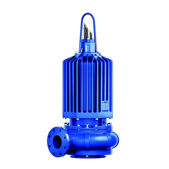
- Page 1 OM-07423-01 June 14, 2021 INSTALLATION, OPERATION, AND MAINTENANCE MANUAL WITH PARTS LIST SUBMERSIBLE PUMP MODEL SF6G GORMAN‐RUPP PUMPS www.grpumps.com 2021 Gorman‐Rupp Pumps Printed in U.S.A.
- Page 2 Register your new Gorman‐Rupp pump online at www.grpumps.com Valid serial number and e‐mail address required. RECORD YOUR PUMP MODEL AND SERIAL NUMBER Please record your pump model and serial number in the spaces provided below. Your Gorman‐Rupp distributor needs this information when you require parts or service. Pump Model: Serial Number:...
-
Page 3: Table Of Contents
TABLE OF CONTENTS INTRODUCTION ..........PAGE I - 1 SAFETY ‐... - Page 4 TABLE OF CONTENTS (continued) PARTS LISTS: Pump Model Assembly ..........PAGE E - 3 Motor Assemblies .
-
Page 5: Introduction
SF SERIES OM-07423 INTRODUCTION Thank You for purchasing a Gorman‐Rupp pump. HAZARD AND INSTRUCTION Read this manual carefully to learn how to safely DEFINITIONS install and operate your pump. Failure to do so could result in personal injury or damage to the The following are used to alert maintenance per... -
Page 6: Safety - Section A
SF SERIES OM-07423 SAFETY - SECTION A This information applies to the SF Se ries submersible pump indicated on the front cover of this manual. The electrical power used to operate In addition to this manual, see the sepa this pump is high enough to cause inju rate literature covering the control box, ry or death. - Page 7 OM-07423 SF SERIES in this warning could result in injury or death to personnel. The electrical power used to operate this pump is high enough to cause inju ry or death. Make certain that the control Death or serious personal injury and handle on the control box is in the OFF damage to the pump or components position and locked out, or that the pow...
- Page 8 SF SERIES OM-07423 Do not remove plates, covers, gauges, After the pump has been installed, make pipe plugs, or fittings from an over certain that the pump and all piping or heated pump. Vapor pressure within the pump can cause parts being disen hose connections are secure before op...
-
Page 9: Installation - Section B
SF SERIES OM-07423 INSTALLATION - SECTION B Review all SAFETY information in Section A. match the ratings on the control box and in coming power. Since pump installations are seldom identical, this e. Carefully read all tags, decals, and markings section is intended only to summarize general rec... -
Page 10: Lifting
MODEL VOLTAGE/ SIZE H.P . MOTOR LOCKED PHASE LOAD ROTOR AMPS AMPS SF6G 460/575 6” 75.0 1750 86/69 542/434 PELLER ROTATION, SECTION C. Lifting This pump may be mounted on guide rails or cables for use with optional discharge elbow/base... -
Page 11: Piping
SF SERIES OM-07423 Regardless of the installation configuration, the Field Wiring Connections (Incoming Power) maximum recommended submergence depth Field wiring is not provided with this pump, and is 65 feet (20 meters). must be supplied by the user. The field wiring must After installation in the wet well, reel in any slack in be of the proper size and type to ensure an ade... -
Page 12: Liquid Level Devices
OM-07423 SF SERIES This pump is shipped completely wired for the volt age shown on the nameplate and is ready for op eration through an approved control box. Ground the control box in accordance with the in structions accompanying it. Figure B-2. - Page 13 SF SERIES OM-07423 Other types of liquid level devices may also be enough to allow 6 minutes between starts. used. Consult the factory for the liquid level device If the pump motor cycles more than 10 best suited for your application. starts per hour, it will over‐heat, resulting in damage to the motor windings or control box components.
-
Page 14: Operation - Section C
SF SERIES OM-07423 OPERATION - SECTION C GENERAL INFORMATION pendent upon the quality and performance of the electrical controls, the pump warran Review all SAFETY information in Section A. ty is valid only when controls have been specified or provided by The Gorman‐ Rupp Company. - Page 15 OM-07423 SF SERIES SF6G 460/575V 3P PERFORMANCE CURVE PAGE C - 2 OPERATION...
-
Page 16: Control Box
SF SERIES OM-07423 Control Box 2. Lock out the power to the control panel to ensure that the pump will Control boxes are available as optional equipment remain inoperative. from the factory. The control boxes contain con 3. Allow the pump to completely cool trols for starting and stopping the pump, and pro... -
Page 17: Impeller Rotation
OM-07423 SF SERIES burns and injuries. If overheating of the ry or death. Make certain that incoming pump occurs: power is off and locked out before inter changing motor leads. 1. Stop the pump immediately. 2. Ventilate the area. 3. Allow the pump to completely cool. 4. - Page 18 SF SERIES OM-07423 between starts, it will over‐heat, resulting in damage to the motor windings. Stopping To avoid serious damage to the pump, check for unusual noises or excessive vi bration while the pump is running. If noise Follow the instructions accompanying the control or vibration is excessive, stop operation box for stopping the pump.
-
Page 19: Cold Weather Preservation
OM-07423 SF SERIES Check the oil level(s) as indicated in the following this, check the oil level in the seal cavity after the LUBRICATION section. first two weeks of operation, and every month thereafter. COLD WEATHER PRESERVATION Before installing or removing the lubrication plugs, always clean the area around the plugs to prevent contamination. -
Page 20: Troubleshooting - Section D
SF SERIES OM-07423 TROUBLESHOOTING - SECTION D Review all SAFETY information in Section A. NOTE Many of the probable remedies listed in the TROU BLESHOOTING CHART require use of electrical test instruments; for specific procedures, see ELECTRICAL TESTING at the end of the chart. TROUBLESHOOTING CHART TROUBLE POSSIBLE CAUSE... - Page 21 OM-07423 SF SERIES TROUBLESHOOTING CHART (cont'd) TROUBLE POSSIBLE CAUSE PROBABLE REMEDY Discharge head too high. Reduce discharge head or install MOTOR RUNS, BUT staging adaptor and additional PUMP FAILS TO DELIVER RATED pump. DISCHARGE. Low or incorrect voltage. Measure control box voltage, both when pump is running and when shut off.
- Page 22 SF SERIES OM-07423 ELECTRICAL TESTING 3. The pump submerged and running under full load. Make the electrical checks which follow to deter The voltage measured under each condition mine if pump malfunctions are being caused by must be the same. problems in the motor or in the motor cable.
- Page 23 OM-07423 SF SERIES motor cable green/yellow ground lead. Touch and 1 megohm, insulation is acceptable but the other test lead to each of the motor cable should be rechecked regularly. If resistance leads in turn. Note the readings. reads less than 1 megohm, insulation should be checked more closely and frequently.
-
Page 24: Pump Maintenance And Repair - Section E
SF SERIES OM-07423 PUMP MAINTENANCE AND REPAIR - SECTION E GENERAL INFORMATION Lifting Review all SAFETY information in Section A. Death or serious personal injury and damage to the pump or components can occur if proper lifting procedures Do not attempt to service the pump as are not observed. - Page 25 OM-07423 SF SERIES ILLUSTRATION PARTS PAGE Figure E-1. SF6G Pump Model Assembly PAGE E - 2 MAINTENANCE AND REPAIR...
- Page 26 SF SERIES OM-07423 SF6G Pump Model Assembly Parts List (From S/N 1753179 Up) If your pump serial number is followed by an “N”, your pump is NOT a standard production model. Contact the Gorman‐Rupp Company to verify part numbers. ITEM...
- Page 27 OM-07423 SF SERIES ILLUSTRATION Figure E-2. Motor Assemblies PAGE E - 4 MAINTENANCE AND REPAIR...
- Page 28 SF SERIES OM-07423 Motor Assemblies Parts List ITEM PART PART NAME NUMBER MOTOR SUB-ASSEMBLY: -460/3 47111-990 --MOTOR HOUSING 38311-217 10000 --STATOR 47113-103 --STUD MC1042 17000 --VOLTAGE TAG 38816-460 -575/3 47111-991 --MOTOR HOUSING 38311-217 10000 --STATOR 47113-104 --STUD MC1042 17000 --VOLTAGE TAG 38816-128 BEARING 23282-010...
- Page 29 OM-07423 SF SERIES PUMP AND SEAL DISASSEMBLY AND cables, or the piping. Attach proper lift ing equipment to the lifting bail fitted on REASSEMBLY the pump. Lift the pump or component only as high as necessary and keep per Review all SAFETY information in Section A. sonnel away from suspended objects.
- Page 30 SF SERIES OM-07423 If the pump is equipped with a trash stand, disen gage the hardware securing the pump to the stand before proceeding with pump disassembly. Use Only Genuine Gorman-Rupp re Suction Head and Wear Ring Removal placement parts. Failure to do so may cre ate a hazard and damage the pump or di...
- Page 31 OM-07423 SF SERIES Lower Seal Removal (Figures E-1 and E-3) Remove the seal spring. Slide the shaft sleeve (14) Let the pump cool before removing the and rotating portion of the seal off the shaft as a seal cavity drain plug. Pressure built up unit.
- Page 32 SF SERIES OM-07423 housing until the female terminal (15) can be ac able, the cause must be determined and corrected cessed. Pull the female terminal off the male termi before reassembly. Replace any parts as required. nal (16) and remove the intermediate, rotor shaft Thoroughly clean all reuseable parts with a soft and bearings from the motor assembly.
- Page 33 OM-07423 SF SERIES ROTOR STATIONARY SHAFT SEAL SEAT ROTATING O‐RING ELEMENT SPRING BELLOWS AND RETAINER ASSY SPRING CENTERING WASHER SEAL RETAINING RING STATIONARY SEAL PLATE SEAL SEAT O‐RING ROTATING BELLOWS AND ELEMENT RETAINER ASSY SPRING SHIM SET SPRING RETAINER IMPELLER Figure E-3.
- Page 34 SF SERIES OM-07423 Position the intermediate so the holes for the against the shaft shoulder. Use caution not to nick mounting hardware in the intermediate align with or damage the O‐ring on the shaft keyway. those in the motor housing and press the inter Position the seal plate on a clean flat surface with mediate into the motor housing until fully seated.
- Page 35 OM-07423 SF SERIES Lubricate the I.D. of the bellows with water and Suction Head and Wear Ring Installation slide the rotating subassembly over the shaft (Figure E-1) sleeve (14) until the seal face is just flush with the undercut end of the sleeve. The suction head (10) and wear ring (6) must be installed in the pump casing (1) before installing Slide the assembled shaft sleeve and rotating por...
- Page 36 SF SERIES OM-07423 ance between the impeller and wear ring. If the handle on the control box is in the off po clearance is too narrow, turn the screws (20) in an sition and locked out, or that the power alternating pattern to push the pump casing and supply to the control box has been suction head away from the impeller until the prop...
- Page 37 OM-07423 SF SERIES Rotor Shaft and Bearing Removal precautions printed on solvent contain ers. (Figure E-2) Rotate the bearings by hand to check for rough See PUMP END DISASSEMBLY, and remove all ness or binding. If rotation is rough, replace the pump end and seal components.
- Page 38 SF SERIES OM-07423 Using two propane heat torches of the type de is recommended that these steps be performed by signed to melt ice or burn weeds from sidewalks at least two people to promote efficient installation and driveways, apply heat quickly and evenly to of the stator.
- Page 39 OM-07423 SF SERIES turns. Tape the stator leads together to protect bent or damaged, or if the laminations are sepa them during installation. rated, replace the shaft and rotor (a single assem bly). NOTE Stator installation involves heating the motor hous ing.
- Page 40 SF SERIES OM-07423 intermediate to the motor housing with the hard race, balls, or ball cage. Press only on the ware (12 and 13). Torque the capscrews to 47 ft. inner race. lbs. (6,5 m. kg.). After the bearings have been installed and allowed to cool, check to ensure that they have not moved Terminal Housing Assembly Installation out of position in shrinking.
- Page 41 OM-07423 SF SERIES housing over the opening in the top of the motor Hoisting Bail Installation housing. (Figure E-1) Check to ensure that the contacts on the ends of If the hoisting bail (27) was removed in order to re the motor stator leads are firmly installed in their re...
- Page 42 SF SERIES OM-07423 See Figure E-4 and connect the vacuum pump or Seal and Motor Cavity Testing compressor/venturi system directly to the pump at the hole for the seal cavity drain plug (7, Figure Connect the vacuum pump or compressor/venturi E-2).
- Page 43 OM-07423 SF SERIES Remove the plug, and screw a short 1/4 inch NPT LUBRICATION nipple into the hole. Plug the open end of the nipple with your finger. Tip the pump and drain off a small Seal Cavity amount of oil into a transparent cup, and stand the pump up again.
- Page 44 For Warranty Information, Please Visit www.grpumps.com/warranty or call: U.S.: 419-755-1280 Canada: 519-631-2870 International: +1-419-755-1352 GORMAN‐RUPP PUMPS...
Need help?
Do you have a question about the SF6G and is the answer not in the manual?
Questions and answers