Table of Contents
Advertisement
Quick Links
Advertisement
Table of Contents

Related Manuals for GORMAN-RUPP PUMPS SF6C


Summary of Contents for GORMAN-RUPP PUMPS SF6C
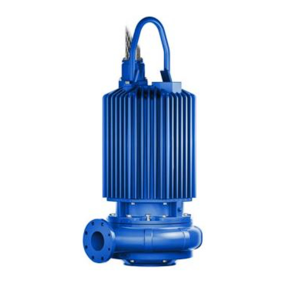
- Page 1 ACDE OM-06604-01 March 25, 2013 INSTALLATION, OPERATION, AND MAINTENANCE MANUAL WITH PARTS LIST SUBMERSIBLE PUMP MODEL SF6C THE GORMAN‐RUPP COMPANY D MANSFIELD, OHIO www.grpumps.com GORMAN‐RUPP OF CANADA LIMITED ST. THOMAS, ONTARIO, CANADA Printed in U.S.A. 2013 The Gorman‐Rupp Company...
- Page 2 Register your new Gorman‐Rupp pump online at www.grpumps.com Valid serial number and e‐mail address required. RECORD YOUR PUMP MODEL AND SERIAL NUMBER Please record your pump model and serial number in the spaces provided below. Your Gorman‐Rupp distributor needs this information when you require parts or service. Pump Model: Serial Number:...
-
Page 3: Table Of Contents
TABLE OF CONTENTS INTRODUCTION ..........PAGE I - 1 SAFETY ‐... - Page 4 TABLE OF CONTENTS (continued) PARTS LISTS: Pump Model Assembly ..........PAGE E - 3 Motor Assemblies .
-
Page 5: Introduction
SF SERIES OM-06604 INTRODUCTION Thank You for purchasing a Gorman‐Rupp SF Se Gorman‐Rupp of Canada Limited ries Pump. Read this manual carefully to learn 70 Burwell Road how to safely install and operate your pump. Fail St. Thomas, Ontario N5P 3R7 ure to do so could result in personal injury or dam... -
Page 6: Safety - Section A
SF SERIES OM-06604 SAFETY - SECTION A This information applies to the SF Se ries submersible pump indicated on the front cover of this manual. The electrical power used to operate In addition to this manual, see the sepa this pump is high enough to cause inju rate literature covering the control box, ry or death. - Page 7 OM-066041 SF SERIES in this warning could result in injury or death to personnel. Never attempt to alter the length or re pair any power cable with a splice. The pump motor and cable must be com pletely waterproof. Injury or death may Do not attempt to lift this pump by the result from alterations.
- Page 8 SF SERIES OM-06604 especially high if operated against a closed discharge valve. Never operate against a closed discharge valve for long periods of time. If this pump is used to handle sewage, take necessary precautions during maintenance and repair to prevent per sonal contamination which could result in illness.
-
Page 9: Installation - Section B
SF SERIES OM-06604 INSTALLATION - SECTION B Review all SAFETY information in Section A. match the ratings on the control box and in coming power. Since pump installations are seldom identical, this e. Carefully read all tags, decals, and markings section is intended only to summarize general rec... -
Page 10: Lifting
VOLTAGE/ SIZE H.P . MOTOR LOCKED PHASE LOAD ROTOR AMPS AMPS SF6C 460/575 6” 30.0 1750 36.6/29.3 246/197 Lifting fully seated in the baseplate. Pump unit weights will vary depending on the To install a pump configured for a guide rail/guide mounting and drive provided. -
Page 11: Electrical Connections
SF SERIES OM-06604 ity, keep the line as short and straight as possible. Motor Cable Grounding Test Elbows and fittings used in a discharge line in crease friction losses; minimize their use. It is recommended that a check valve or throttling valve be installed in the discharge line to control si... -
Page 12: Liquid Level Devices
OM-06604 SF SERIES Refer to Figures B-1 and connect the pump motor Liquid Level Devices cable to the control box. Optional controls available from Gorman‐Rupp may provide a means to automatically regulate the liquid level. These control boxes may be con nected to the following sensing devices which per... - Page 13 SF SERIES OM-06604 PUMP PUMP CONTROL BOX CONTROL BOX TO LEVEL CONTROL CIRCUIT TO LEVEL CONTROL CIRCUIT IN MAIN CONTROL IN MAIN CONTROL LIQUID LEVEL LIQUID LEVEL RANGE RANGE DEWATERING DEWATERING ON (FILLING) ON (FILLING) BULB (FLOAT TYPE) DIAPHRAGM TYPE Figure B-3.
-
Page 14: Operation - Section C
SF SERIES OM-06604 OPERATION - SECTION C GENERAL INFORMATION pendent upon the quality and performance of the electrical controls, the pump warran Review all SAFETY information in Section A. ty is valid only when controls have been specified or provided by The Gorman‐ Rupp Company. - Page 15 OM-06604 SF SERIES SF6C 460/575V 3P PERFORMANCE CURVE PAGE C - 2 OPERATION...
-
Page 16: Control Box
SF SERIES OM-06604 Control Box 2. Lock out the power to the control panel to ensure that the pump will Control boxes are available as optional equipment remain inoperative. from the factory. The control boxes contain con 3. Allow the pump to completely cool trols for starting and stopping the pump, and pro... -
Page 17: Impeller Rotation
OM-06604 SF SERIES burns and injuries. If overheating of the ry or death. Make certain that incoming pump occurs: power is off and locked out before inter changing motor leads. 1. Stop the pump immediately. 2. Ventilate the area. 3. Allow the pump to completely cool. 4. -
Page 18: Cold Weather Preservation
SF SERIES OM-06604 between starts, it will over‐heat, resulting in bration while the pump is running. If noise damage to the motor windings. or vibration is excessive, stop operation and refer to the troubleshooting chart in the Stopping maintenance and repair manual. Follow the instructions accompanying the control The suction inlet or impeller may become clogged box for stopping the pump. -
Page 19: Lubrication
OM-06604 SF SERIES ing a torch or other source of flame. This Before installing or removing the lubrication plugs, always clean the area around the plugs to prevent could damage gaskets, O‐rings or heat contamination. the oil in the seal housing above critical temperatures, causing the pump to rup... -
Page 20: Troubleshooting - Section D
SF SERIES OM-06604 TROUBLESHOOTING - SECTION D Review all SAFETY information in Section A. NOTE Many of the probable remedies listed in the TROU BLESHOOTING CHART require use of electrical test instruments; for specific procedures, see ELECTRICAL TESTING at the end of the chart. TROUBLESHOOTING CHART TROUBLE POSSIBLE CAUSE... - Page 21 OM-06604 SF SERIES TROUBLESHOOTING CHART (cont'd) TROUBLE POSSIBLE CAUSE PROBABLE REMEDY Discharge head too high. Reduce discharge head or install MOTOR RUNS, BUT staging adaptor and additional PUMP FAILS TO DELIVER RATED pump. DISCHARGE. Low or incorrect voltage. Measure control box voltage, both when pump is running and when shut off.
- Page 22 SF SERIES OM-06604 ELECTRICAL TESTING 3. The pump submerged and running under full load. Make the electrical checks which follow to deter The voltage measured under each condition mine if pump malfunctions are being caused by must be the same. problems in the motor or in the motor cable.
- Page 23 OM-06604 SF SERIES motor cable green/yellow ground lead. Touch and 1 megohm, insulation is acceptable but the other test lead to each of the motor cable should be rechecked regularly. If resistance leads in turn. Note the readings. reads less than 1 megohm, insulation should be checked more closely and frequently.
-
Page 24: Pump Maintenance And Repair - Section E
SF SERIES OM-06604 PUMP MAINTENANCE AND REPAIR - SECTION E GENERAL INFORMATION The maintenance and repair instructions in this manual are keyed to the illustrations, Figures E-1 and E-2, and the corresponding parts lists. Review all SAFETY information in Section A. Select a suitable location, preferably indoors, to perform required maintenance. - Page 25 OM-06604 SF SERIES ILLUSTRATION PARTS PAGE Figure E-1. SF6C Pump Model Assembly PAGE E - 2 MAINTENANCE AND REPAIR...
- Page 26 SF SERIES OM-06604 SF6C Pump Model Assembly Parts List (From S/N 1555767 Up) If your pump serial number is followed by an “N”, your pump is NOT a standard production model. Contact the Gorman‐Rupp Company to verify part numbers. ITEM...
- Page 27 OM-06604 SF SERIES ILLUSTRATION Figure E-2. 47111-824 and -825 Motor Assemblies PAGE E - 4 MAINTENANCE AND REPAIR...
- Page 28 SF SERIES OM-06604 47111-824 and -825 Motor Assemblies Parts List ITEM PART MAT'L PART NAME NUMBER CODE MOTOR SUBASSEMBLY -460/3 47111-840 --MOTOR HOUSING 38311-215 10000 --STATOR 47113-097 --TERMINAL HOUSING STUD MC1042 17000 --VOLTAGE TAG 38816-460 --ROTATION DECAL 38815-027 -575/3 47111-841 --MOTOR HOUSING 38311-215 10000...
- Page 29 OM-06604 SF SERIES Select a suitable location, preferably indoors, to PUMP AND SEAL DISASSEMBLY AND perform required maintenance. All work must be REASSEMBLY performed by qualified personnel. Review all SAFETY information in Section A. Check the chart in TROUBLESHOOTING, Section D of this manual, to determine the nature of the This pump requires little service due to its rugged, pump problem.
- Page 30 SF SERIES OM-06604 Pump Casing Removal (Figure E-1) Position the pump assembly on a flat surface and Do not attempt to lift the pump by the use the lifting bail and lifting device to support the motor power cable or the piping. Attach pump in a vertical position.
- Page 31 OM-06604 SF SERIES move the impeller screw (4). Remove the impeller If no further disassembly is required, proceed to washer (3). Remove the metal rod from between the appropriate areas in PUMP END REASSEMB the vanes of the impeller. NOTE Upper Seal Removal An alternate method of removing the impeller screw (Figures E-2 and E-3)
- Page 32 SF SERIES OM-06604 PUMP END REASSEMBLY precautions printed on solvent contain ers. NOTE Inspect the rotor shaft (3, Figure E-2) for dam Reuse of old O‐rings or shaft seal parts will result in aged threads, scoring, or nicks. Remove nicks and premature leakage or reduced pump performance.
- Page 33 OM-06604 SF SERIES ROTOR STATIONARY SHAFT SEAL SEAT ROTATING O‐RING ELEMENT SPRING BELLOWS AND RETAINER ASSY SPRING CENTERING WASHER SEAL RETAINING RING STATIONARY SEAL PLATE SEAL SEAT O‐RING ROTATING BELLOWS AND ELEMENT RETAINER ASSY SPRING SHIM SET SPRING RETAINER IMPELLER Figure E-3.
- Page 34 SF SERIES OM-06604 Position the intermediate so the holes for the against the shaft shoulder. Use caution not to nick mounting hardware in the intermediate align with or damage the O‐ring on the shaft keyway. those in the motor housing and press the inter Position the seal plate on a clean flat surface with mediate into the motor housing until fully seated.
- Page 35 OM-06604 SF SERIES Lubricate the I.D. of the bellows with water and the pump casing in order to set the impeller‐to‐ slide the rotating subassembly over the shaft wear ring clearance. sleeve (25) until the seal face is just flush with the If the wear ring was removed from the suction undercut end of the sleeve.
- Page 36 SF SERIES OM-06604 er clearance is achieved. If the clearance is too otherwise cut off and locked out, before wide, use the hardware (8 and 11) to draw the attempting to open or service the pump pump casing and suction head toward the impeller assembly.
- Page 37 OM-06604 SF SERIES Rotor Shaft and Bearing Removal precautions printed on solvent contain ers. (Figure E-2) Rotate the bearings by hand to check for rough See PUMP END DISASSEMBLY, and remove all ness or binding. If rotation is rough, replace the pump end and seal components.
- Page 38 SF SERIES OM-06604 Using two propane heat torches of the type de is recommended that these steps be performed by signed to melt ice or burn weeds from sidewalks at least two people to promote efficient installation and driveways, apply heat quickly and evenly to of the stator.
- Page 39 OM-06604 SF SERIES turns. Tape the stator leads together to protect bent or damaged, or if the laminations are sepa them during installation. rated, replace the shaft and rotor (a single assem bly). NOTE Stator installation involves heating the motor hous ing.
- Page 40 SF SERIES OM-06604 intermediate to the motor housing with the hard race, balls, or ball cage. Press only on the ware (11 and 12). Torque the capscrews to 47 ft. inner race. lbs. (6,5 m. kg.). After the bearings have been installed and allowed to cool, check to ensure that they have not moved Terminal Housing Assembly Installation out of position in shrinking.
- Page 41 OM-06604 SF SERIES housing over the opening in the top of the motor Hoisting Bail Installation housing. (Figure E-1) Check to ensure that the contacts on the ends of If the hoisting bail (19) was removed in order to re the motor stator leads are firmly installed in their re...
- Page 42 SF SERIES OM-06604 See Figure E-4 and connect the vacuum pump or Seal and Motor Cavity Testing compressor/venturi system directly to the pump at the hole for the seal cavity drain plug (7, Figure Connect the vacuum pump or compressor/venturi E-2).
- Page 43 OM-06604 SF SERIES Remove the plug, and screw a short 1/4 inch NPT LUBRICATION nipple into the hole. Plug the open end of the nipple with your finger. Tip the pump and drain off a small Seal Cavity amount of oil into a transparent cup, and stand the pump up again.
- Page 44 For U.S. and International Warranty Information, Please Visit www.grpumps.com/warranty or call: U.S.: 419-755-1280 International: +1-419-755-1352 For Canadian Warranty Information, Please Visit www.grcanada.com/warranty or call: 519-631-2870 THE GORMAN‐RUPP COMPANY D MANSFIELD, OHIO GORMAN‐RUPP OF CANADA LIMITED ST. THOMAS, ONTARIO, CANADA...
Need help?
Do you have a question about the SF6C and is the answer not in the manual?
Questions and answers