Table of Contents
Advertisement
Quick Links
ACDE
INSTALLATION, OPERATION,
AND MAINTENANCE MANUAL
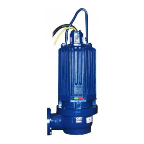
DRY PIT SUBMERSIBLE PUMP
THE GORMAN‐RUPP COMPANY D MANSFIELD, OHIO
GORMAN‐RUPP OF CANADA LIMITED
WITH PARTS LIST
MODEL
SFDV4B
www.grpumps.com
D
ST. THOMAS, ONTARIO, CANADA
e
2011 The Gorman‐Rupp Company
OM-06407-01
July 14, 2011
Rev. B 01‐09‐14
Printed in U.S.A.
Advertisement
Table of Contents

Related Manuals for GORMAN-RUPP PUMPS SFDV4B


Summary of Contents for GORMAN-RUPP PUMPS SFDV4B
- Page 1 July 14, 2011 Rev. B 01‐09‐14 INSTALLATION, OPERATION, AND MAINTENANCE MANUAL WITH PARTS LIST DRY PIT SUBMERSIBLE PUMP MODEL SFDV4B THE GORMAN‐RUPP COMPANY D MANSFIELD, OHIO www.grpumps.com GORMAN‐RUPP OF CANADA LIMITED ST. THOMAS, ONTARIO, CANADA Printed in U.S.A. 2011 The Gorman‐Rupp Company...
- Page 2 Register your new Gorman‐Rupp pump online at www.grpumps.com Valid serial number and e‐mail address required. RECORD YOUR PUMP MODEL AND SERIAL NUMBER Please record your pump model and serial number in the spaces provided below. Your Gorman‐Rupp distributor needs this information when you require parts or service. Pump Model: Serial Number:...
-
Page 3: Table Of Contents
TABLE OF CONTENTS INTRODUCTION ..........PAGE I - 1 SAFETY ‐... - Page 4 TABLE OF CONTENTS (continued) PARTS LISTS: Pump Model Assembly ..........PAGE E - 3 Motor Assemblies .
-
Page 5: Introduction
SF SERIES OM-06407 INTRODUCTION Thank You for purchasing a Gorman‐Rupp SF Se St. Thomas, Ontario N5P 3R7 ries Pump. Read this manual carefully to learn Phone: (519) 631-2870 how to safely install and operate your pump. Fail ure to do so could result in personal injury or dam age to the pump. -
Page 6: Safety - Section A
SF SERIES OM-06407 SAFETY - SECTION A This information applies to the SF Se ries dry pit submersible pump indicated on the front cover of this manual. The electrical power used to operate In addition to this manual, see the sepa this pump is high enough to cause inju... - Page 7 OM-06407 SF SERIES to the incoming power lines. The pump motor is designed to operate through a Gorman‐Rupp approved control box which provides overload protection and power control; otherwise, the pump The electrical power used to operate warranty will be voided. Make certain this pump is high enough to cause inju...
- Page 8 SF SERIES OM-06407 Do not remove plates, covers, gauges, After the pump has been installed, make pipe plugs, or fittings from an over certain that the pump and all piping or heated pump. Vapor pressure within the pump can cause parts being disen hose connections are secure before op...
-
Page 9: Installation - Section B
SF SERIES OM-06407 INSTALLATION - SECTION B Review all SAFETY information in Section A. PUMP SEALS Since pump installations are seldom identical, this This pump is equipped with two mechanical seals. section is intended only to summarize general rec The lower seal is lubricated by the liquid being ommendations and practices required to inspect, pumped and prevents the liquid from entering the position, and arrange the pump and piping. -
Page 10: Lifting
OM-06407 SF SERIES TABLE B-1. PUMP MOTOR SPECIFICATIONS MODEL VOLTAGE/ SIZE H.P . MOTOR LOCKED PHASE LOAD ROTOR AMPS AMPS SFDV4B 208/3 4” 1750 22.0 184.7 SFDV4B 230‐460‐575/3 4” 1750 22.2/11.1/8.88 167.0/83.5/66.8 Lifting Piping NOTE Pump unit weights will vary depending on the Refer to Pump Performance in OPERATION - mounting and drive provided. -
Page 11: Field Wiring Connections (Incoming Power)
SF SERIES OM-06407 or death to personnel can result from Motor Cable Grounding Test any alteration to the cable. Field Wiring Connections (Incoming Power) Do not connect the pump power or con Field wiring is not provided with this pump, and trol cables to the control box or incom... -
Page 12: Liquid Level Devices
OM-06407 SF SERIES Refer to Figure B-1 and connect the pump motor desirable, connect only to controls which cable to the control box. are wired for manual restart. Refer to the appropriate wiring diagram accompa nying the control box when making electrical con nections. - Page 13 SF SERIES OM-06407 PUMP PUMP CONTROL BOX CONTROL BOX TO LEVEL CONTROL CIRCUIT TO LEVEL CONTROL CIRCUIT IN MAIN CONTROL IN MAIN CONTROL LIQUID LEVEL LIQUID LEVEL RANGE RANGE DEWATERING DEWATERING ON (FILLING) ON (FILLING) BULB (FLOAT TYPE) DIAPHRAGM TYPE Figure B-3.
-
Page 14: Operation - Section C
SF SERIES OM-06407 OPERATION - SECTION C GENERAL INFORMATION pendent upon the quality and performance of the electrical controls, the pump warran Review all SAFETY information in Section A. ty is valid only when controls have been specified or provided by The Gorman‐ Rupp Company. - Page 15 OM-06407 SF SERIES SFDV4B 230/460/575V 3P PERFORMANCE CURVE PAGE C - 2 OPERATION...
- Page 16 SF SERIES OM-06407 SFDV4B 208V 3P PERFORMANCE CURVE OPERATION PAGE C - 3...
-
Page 17: Control Box
OM-06407 SF SERIES Control Box 2. Lock out the power to the control panel to ensure that the pump will Control boxes are available as optional equipment remain inoperative. from the factory. The control boxes contain con 3. Allow the pump to completely cool trols for starting and stopping the pump, and pro... -
Page 18: Impeller Rotation
SF SERIES OM-06407 burns and injuries. If overheating of the ry or death. Make certain that incoming pump occurs: power is off and locked out before inter changing motor leads. 1. Stop the pump immediately. 2. Ventilate the area. 3. Allow the pump to completely cool. 4. - Page 19 OM-06407 SF SERIES between starts, it will over‐heat, resulting in check for unusual noises or excessive vi damage to the motor windings. bration while the pump is running. If noise or vibration is excessive, stop operation Stopping and refer to the troubleshooting chart in the maintenance and repair manual.
-
Page 20: Cold Weather Preservation
SF SERIES OM-06407 COLD WEATHER PRESERVATION first two weeks of operation, and every month thereafter. Before installing or removing the lubrication plugs, always clean the area around the plugs to prevent contamination. Do not attempt to thaw the pump by us Draining Oil ing a torch or other source of flame. -
Page 21: Troubleshooting - Section D
SF SERIES OM-06407 TROUBLESHOOTING - SECTION D Review all SAFETY information in Section A. NOTE Many of the probable remedies listed in the TROU BLESHOOTING CHART require use of electrical test instruments; for specific procedures, see ELECTRICAL TESTING at the end of the chart. TROUBLESHOOTING CHART TROUBLE POSSIBLE CAUSE... - Page 22 OM-06407 SF SERIES TROUBLESHOOTING CHART (cont'd) TROUBLE POSSIBLE CAUSE PROBABLE REMEDY Discharge head too high. Reduce discharge head or install MOTOR RUNS, BUT staging adaptor and additional PUMP FAILS TO DELIVER RATED pump. DISCHARGE. Low or incorrect voltage. Measure control box voltage, both when pump is running and when shut off.
- Page 23 SF SERIES OM-06407 ELECTRICAL TESTING 3. The pump submerged and running under full load. Make the electrical checks which follow to deter The voltage measured under each condition mine if pump malfunctions are being caused by must be the same. problems in the motor or in the motor cable.
- Page 24 OM-06407 SF SERIES motor cable green/yellow ground lead. Touch and 1 megohm, insulation is acceptable but the other test lead to each of the motor cable should be rechecked regularly. If resistance leads in turn. Note the readings. reads less than 1 megohm, insulation should be checked more closely and frequently.
-
Page 25: Pump Maintenance And Repair - Section E
SF SERIES OM-06407 PUMP MAINTENANCE AND REPAIR - SECTION E GENERAL INFORMATION The maintenance and repair instructions in this manual are keyed to the illustrations, Figures E-1 and E-2, and the corresponding parts lists. Review all SAFETY information in Section A. Select a suitable location, preferably indoors, to perform required maintenance. - Page 26 OM-06407 SF SERIES ILLUSTRATION PARTS PAGE Figure E-1. SFDV4B Pump Model Assembly PAGE E - 2 MAINTENANCE AND REPAIR...
- Page 27 SF SERIES OM-06407 SFDV4B Pump Model Assembly Parts List (From S/N 1520149 Up) If your pump serial number is followed by an “N”, your pump is NOT a standard production model. Contact the Gorman‐Rupp Company to verify part numbers. ITEM...
- Page 28 OM-06407 SF SERIES ILLUSTRATION Figure E-2. 47111-810, -811 and -812 Motor Assemblies PAGE E - 4 MAINTENANCE AND REPAIR...
- Page 29 SF SERIES OM-06407 47111-810, -811 and -812 Motor Assemblies Parts List ITEM PART NAME PART MAT'L ITEM PART NAME PART MAT'L NUMBER CODE NUMBER CODE MOTOR SUBASSEMBLY INTERMEDIATE 38261-035 10000 -208‐230/3 47111-835 SEAL ASSY S1934 --MOTOR HOUSING 38311-067 10000 SNAP RING S245 --STATOR 47113-093...
- Page 30 OM-06407 SF SERIES Select a suitable location, preferably indoors, to PUMP AND SEAL DISASSEMBLY AND perform required maintenance. All work must be REASSEMBLY performed by qualified personnel. Review all SAFETY information in Section A. Check the chart in TROUBLESHOOTING, Section D of this manual, to determine the nature of the This pump requires little service due to its rugged, pump problem.
- Page 31 SF SERIES OM-06407 seal cavity drain plug. Pressure built up within a hot pump could cause the oil to spray out when the plug is removed. Re move the plug slowly and permit pressure Do not attempt to lift the pump by the to vent to atmosphere.
- Page 32 OM-06407 SF SERIES Apply oil to the sleeve and work it up under the rub Remove the snap ring (4) from the groove in the in ber bellows. Slide the rotating portion of the seal off termediate and pull the assembled rotor shaft and the shaft sleeve.
- Page 33 SF SERIES OM-06407 tallic parts in fresh cleaning solvent and allow to dry precautions printed on solvent contain thoroughly. ers. Handle the seal parts with extreme care to prevent Inspect the rotor shaft (3, Figure E-2) for dam damage. Be careful not to contaminate the preci aged threads, scoring, or nicks.
- Page 34 OM-06407 SF SERIES Clean the rotor shaft (3) and seal cavity area of the face to ensure that it is clean and dry. If cleaning is intermediate (8). Be sure the area is dry and free of necessary, use clean tissue to wipe lightly in a cir lint and dirt.
- Page 35 SF SERIES OM-06407 the seal face to ensure that it is clean and dry. If Impeller Installation cleaning is necessary, use clean tissue to wipe (Figure E-1) lightly in a circular pattern. Inspect the impeller (2) for cracks, broken vanes, NOTE or wear from erosion and replace it if damaged.
- Page 36 OM-06407 SF SERIES Terminal Housing Assembly Removal MOTOR DISASSEMBLY (Figure E-1) The terminal housing assembly (10) may be re Disassembly of the motor is rarely required except placed without disassembling the motor or pump to replace the motor rotor, stator or bearings. Do end components.
- Page 37 SF SERIES OM-06407 Remove the snap ring (4) from the groove in the in Stator Removal termediate and pull the assembled rotor shaft and (Figure E-2) bearings out of the intermediate. Stator replacement requires specialized To prevent damage during removal from equipment, experience with electric mo...
- Page 38 OM-06407 SF SERIES MOTOR REASSEMBLY precautions printed on solvent contain ers. After the motor housing is thoroughly cleaned, po sition it on a flat surface and secure it in an inverted position. Do not unwrap the stator until the motor housing has been prepared for stator installation.
- Page 39 SF SERIES OM-06407 oil and the container must be absolutely clean. If terminal housing opening. Carefully lower the sta the oil has been previously used, it must be thor tor into the motor housing until fully seated against oughly filtered. the housing shoulder.
- Page 40 OM-06407 SF SERIES precautions printed on solvent contain vices of a qualified electrician to make ers. electrical connections. Position the intermediate with the impeller end Secure the pump in upright position with the hoist down on some wood blocks tall enough to allow for ing bail and terminal housing assembly removed.
- Page 41 SF SERIES OM-06407 the terminal housing is fully seated in the motor ing with the hardware (8 and 13). Torque the caps housing. Torque the hex nuts (11) to 27 ft. lbs. (3,7 crews to 47 ft. lbs. (6,5 m. kg.). m.
- Page 42 OM-06407 SF SERIES cavity vacuum down as far as the system will allow, the upper seal stationary seat, resulting in then draw the seal cavity down so the differential seal leakage. between the two cavities is the same as the differ ential between the vacuum readings shown in the Seal and Motor Cavity Testing table.
- Page 43 SF SERIES OM-06407 To check the seal cavity oil, clean any dirt from nipple, top off the seal cavity with oil, and reinstall the level plug. around the seal cavity drain plug (7, Figure E-2). Remove the plug, and screw a short 1/4 inch NPT When lubricating a dry (overhauled) pump, posi...
- Page 44 For U.S. and International Warranty Information, Please Visit www.grpumps.com/warranty or call: U.S.: 419-755-1280 International: +1-419-755-1352 For Canadian Warranty Information, Please Visit www.grcanada.com/warranty or call: 519-631-2870 THE GORMAN‐RUPP COMPANY D MANSFIELD, OHIO GORMAN‐RUPP OF CANADA LIMITED ST. THOMAS, ONTARIO, CANADA...
Need help?
Do you have a question about the SFDV4B and is the answer not in the manual?
Questions and answers