
Related Manuals for GORMAN-RUPP PUMPS SFV4A


Summary of Contents for GORMAN-RUPP PUMPS SFV4A
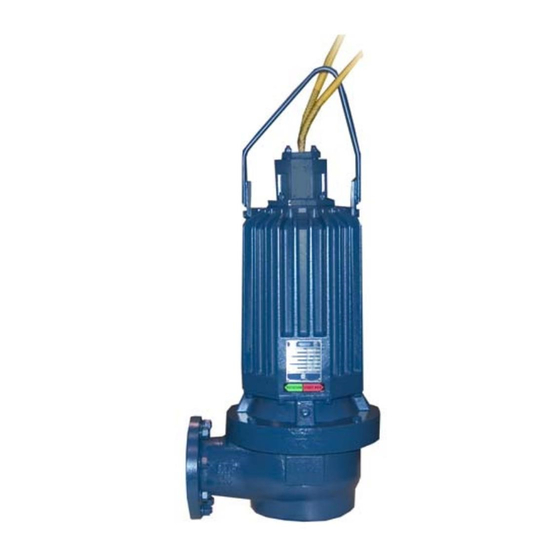
- Page 1 OM-06401-02 August 23, 2022 INSTALLATION, OPERATION, AND MAINTENANCE MANUAL WITH PARTS LIST SUBMERSIBLE PUMP MODEL SFV4A & SFEV4A GORMAN‐RUPP PUMPS www.grpumps.com 2022 Gorman‐Rupp Pumps Printed in U.S.A.
- Page 2 Register your new Gorman‐Rupp pump online at www.grpumps.com Valid serial number and e‐mail address required. RECORD YOUR PUMP MODEL AND SERIAL NUMBER Please record your pump model and serial number in the spaces provided below. Your Gorman‐Rupp distributor needs this information when you require parts or service. Pump Model: Serial Number:...
-
Page 3: Table Of Contents
TABLE OF CONTENTS INTRODUCTION ..........PAGE I - 1 SAFETY ‐... - Page 4 TABLE OF CONTENTS (continued) PARTS LISTS: Pump Model Assembly ..........PAGE E - 3 Motor Assemblies .
-
Page 5: Introduction
SF SERIES OM-06401 INTRODUCTION Thank You for purchasing a Gorman‐Rupp pump. HAZARD AND INSTRUCTION Read this manual carefully to learn how to safely DEFINITIONS install and operate your pump. Failure to do so could result in personal injury or damage to the The following are used to alert maintenance per... -
Page 6: Safety - Section A
SF SERIES OM-06401 SAFETY - SECTION A This information applies to the SF Se ries submersible pump indicated on the front cover of this manual. The electrical power used to operate In addition to this manual, see the sepa this pump is high enough to cause inju rate literature covering the control box, ry or death. - Page 7 OM-06401 SF SERIES to the incoming power lines. The pump electrical ground. Be sure that the in motor is designed to operate through a coming power matches the voltage and Gorman‐Rupp approved control box phase of the pump and control before which provides overload protection and connecting the power source.
- Page 8 SF SERIES OM-06401 approved by the manufacturer, can re sult in severe injury or death and void warranty. Do not remove plates, covers, gauges, pipe plugs, or fittings from an over heated pump. Vapor pressure within the pump can cause parts being disen After the pump has been installed, make gaged to be ejected with great force.
-
Page 9: Installation - Section B
SF SERIES OM-06401 INSTALLATION - SECTION B Review all SAFETY information in Section A. match the ratings on the control box and in coming power. Since pump installations are seldom identical, this e. Carefully read all tags, decals, and markings section is intended only to summarize general rec... -
Page 10: Lifting
See Table B-1 for motor specifications. TABLE B-1. PUMP MOTOR SPECIFICATIONS MODEL VOLTAGE/ SIZE H.P . MOTOR LOCKED PHASE LOAD ROTOR AMPS AMPS SFV4A, SFEV4A 230/1 4” 1750 18.2 80.6 SFV4A, SFEV4A 208/3 4” 1750 12.2 106.1 SFV4A, SFEV4A 230‐460‐575/3 4”... -
Page 11: Piping
SF SERIES OM-06401 shoe engages the discharge elbow/baseplate, it and all local codes. Have a qualified will form an automatic seal. electrician perform all checks and con nections in this section. If the pump is mounted on a trash stand, secure a Never attempt to alter the length of the discharge hose or pipe to the optional discharge pump motor cable or to repair it with a... -
Page 12: Motor Cable Grounding Test
OM-06401 SF SERIES thorized Gorman‐Rupp repair facility only. Otherwise, damage to the pump and injury or death to personnel can re sult. Ground the pump using the power cable ground wire(s) before applying line po Motor Cable Grounding Test tential. Failure to properly ground the pump could result in damage to the pump or control and/or injury or death to personnel. -
Page 13: Liquid Level Devices
SF SERIES OM-06401 are different for filling and dewatering func tions. Be sure to follow the instructions in cluded with the option before making con nections. The thermal protection contacts will auto matically reclose when the motor cools to Diaphragm Type: two fixed‐position sen the established safe operating tempera... -
Page 14: Operation - Section C
SF SERIES OM-06401 OPERATION - SECTION C GENERAL INFORMATION pendent upon the quality and performance of the electrical controls, the pump warran Review all SAFETY information in Section A. ty is valid only when controls have been specified or provided by The Gorman‐ Rupp Company. - Page 15 OM-06401 SF SERIES SFV4A 230/460/575V 3P PERFORMANCE CURVE PAGE C - 2 OPERATION...
- Page 16 SF SERIES OM-06401 SFV4A 208V 3P PERFORMANCE CURVE OPERATION PAGE C - 3...
- Page 17 OM-06401 SF SERIES SFV4A 230V 1P PERFORMANCE CURVE PAGE C - 4 OPERATION...
- Page 18 SF SERIES OM-06401 SFEV4A 230/460/575V 3P PERFORMANCE CURVE OPERATION PAGE C - 5...
- Page 19 OM-06401 SF SERIES SFEV4A 208V 3P PERFORMANCE CURVE PAGE C - 6 OPERATION...
- Page 20 SF SERIES OM-06401 SFEV4A 230V 1P PERFORMANCE CURVE OPERATION PAGE C - 7...
-
Page 21: Control Box
OM-06401 SF SERIES Control Box 2. Lock out the power to the control panel to ensure that the pump will Control boxes are available as optional equipment remain inoperative. from the factory. The control boxes contain con 3. Allow the pump to completely cool trols for starting and stopping the pump, and pro... -
Page 22: Impeller Rotation
SF SERIES OM-06401 burns and injuries. If overheating of the ry or death. Make certain that incoming pump occurs: power is off and locked out before inter changing motor leads. 1. Stop the pump immediately. 2. Ventilate the area. 3. Allow the pump to completely cool. 4. - Page 23 OM-06401 SF SERIES between starts, it will over‐heat, resulting in damage to the motor windings. Stopping To avoid serious damage to the pump, check for unusual noises or excessive vi bration while the pump is running. If noise Follow the instructions accompanying the control or vibration is excessive, stop operation box for stopping the pump.
-
Page 24: Cold Weather Preservation
SF SERIES OM-06401 Check the oil level(s) as indicated in the following On a new pump, check the oil level in the seal cav LUBRICATION section. ity before initial startup, and drain and replace the oil after the first 200 hours of operation. Following this, check the oil level in the seal cavity after the COLD WEATHER PRESERVATION first two weeks of operation, and every month... - Page 25 OM-06401 SF SERIES in Draining Oil. Add premium quality submersible pump oil through the fill plug hole until the oil is lev el with the bottom of the plug hole. Install and tighten the fill plug. PAGE C - 12 OPERATION...
-
Page 26: Troubleshooting - Section D
SF SERIES OM-06401 TROUBLESHOOTING - SECTION D Review all SAFETY information in Section A. NOTE Many of the probable remedies listed in the TROU BLESHOOTING CHART require use of electrical test instruments; for specific procedures, see ELECTRICAL TESTING at the end of the chart. TROUBLESHOOTING CHART TROUBLE POSSIBLE CAUSE... - Page 27 OM-06401 SF SERIES TROUBLESHOOTING CHART (cont'd) TROUBLE POSSIBLE CAUSE PROBABLE REMEDY Discharge head too high. Reduce discharge head or install MOTOR RUNS, BUT staging adaptor and additional PUMP FAILS TO DELIVER RATED pump. DISCHARGE. Low or incorrect voltage. Measure control box voltage, both when pump is running and when shut off.
-
Page 28: Electrical Testing
SF SERIES OM-06401 ELECTRICAL TESTING 3. The pump submerged and running under full load. Make the electrical checks which follow to deter The voltage measured under each condition mine if pump malfunctions are being caused by must be the same. problems in the motor or in the motor cable. - Page 29 OM-06401 SF SERIES motor cable green/yellow ground lead. Touch and 1 megohm, insulation is acceptable but the other test lead to each of the motor cable should be rechecked regularly. If resistance leads in turn. Note the readings. reads less than 1 megohm, insulation should be checked more closely and frequently.
-
Page 30: Pump Maintenance And Repair - Section E
SF SERIES OM-06401 PUMP MAINTENANCE AND REPAIR - SECTION E GENERAL INFORMATION Lifting Review all SAFETY information in Section A. Death or serious personal injury and damage to the pump or components can occur if proper lifting procedures are not observed. Make certain that hoists, chains, slings or cables are in good working condition and of suffi... - Page 31 OM-06401 SF SERIES ILLUSTRATION PARTS PAGE Figure E-1. SFV4A & SFEV4A Pump Model Assembly PAGE E - 2 MAINTENANCE AND REPAIR...
- Page 32 SF SERIES OM-06401 SFV4A & SFEV4A Pump Model Assembly Parts List (From S/N 1814865 Up) If your pump serial number is followed by an “N”, your pump is NOT a standard production model. Contact the Gorman‐Rupp Company to verify part numbers.
- Page 33 OM-06401 SF SERIES ILLUSTRATION Figure E-2. Motor Assemblies PAGE E - 4 MAINTENANCE AND REPAIR...
- Page 34 SF SERIES OM-06401 Motor Assemblies Parts List ITEM PART PART NAME NUMBER STATOR/HOUSING SUB-ASSEMBLY: -230V/1P 47113-118 --MOTOR HOUSING 38311-066 10000 --STATOR 47113-106 --TERMINAL HOUSING STUD MC1042 17000 --ROTATION DECAL 38815-027 -208‐230V/3P , 460V/3P 47113-119 --MOTOR HOUSING 38311-066 10000 --STATOR 47113-091 --TERMINAL HOUSING STUD MC1042 17000 --ROTATION DECAL...
-
Page 35: Pump And Seal Disassembly And Reassembly
OM-06401 SF SERIES PUMP AND SEAL DISASSEMBLY AND the pump. Lift the pump or component only as high as necessary and keep per REASSEMBLY sonnel away from suspended objects. Review all SAFETY information in Section A. This pump requires little service due to its rugged, minimum‐maintenance design. -
Page 36: Pump End Disassembly
SF SERIES OM-06401 was faulty or questionable, the cause must be de Pump Casing Removal termined and corrected before reassembly. All O‐ (Figure E-1) rings must be replaced if disturbed. Position the pump assembly on a flat surface and use the lifting bail and lifting device to support the pump in a vertical position. - Page 37 OM-06401 SF SERIES move the O‐ring (6) and press the stationary ele NOTE ment and seat out of the seal plate from the back A strap wrench may also be used to immobilize the side. impeller. Upper Seal Removal Remove the impeller nut (4). (Figures E-2 and E-3) NOTE Unless cracked or otherwise worn, it is not neces...
- Page 38 SF SERIES OM-06401 Cleaning and Inspection of Pump Parts Inspect the rotor shaft (3, Figure E-2) for dam aged threads, scoring, or nicks. Remove nicks and (Figures E-1 and E-2) burrs with a fine file or hand honing stone to restore original contours.
- Page 39 OM-06401 SF SERIES ROTOR STATIONARY SHAFT SEAL SEAT ROTATING STATIONARY ELEMENT ELEMENT SPRING BELLOWS AND RETAINER ASSY SPRING CENTERING SEAL WASHER RETAINING RING STATIONARY SEAL SEAT STATIONARY SEAL PLATE ELEMENT BELLOWS AND ROTATING RETAINER ASSY ELEMENT SPRING SHIM SET SPRING RETAINER IMPELLER Figure E-3.
- Page 40 SF SERIES OM-06401 hold the element in position until the seal is in necessary, use clean tissue to wipe lightly in a cir stalled. Assemble the drive grooves of the rotating cular pattern. element into the drive lugs of the bellows retainer. Install a new O‐ring (6) on the shoulder of the inter...
-
Page 41: Motor Disassembly
OM-06401 SF SERIES Install the seal spring over the bellows retainer and Final Assembly install the spring retainer (19). See Figure E-3 for If the pump guide shoe was removed for disassem proper order of seal assembly. bly, install a new guide shoe seal and secure the seal and guide shoe to the pump casing with the Impeller Installation previously removed hardware. - Page 42 SF SERIES OM-06401 Terminal Housing Assembly Removal Remove the snap ring (4) from the groove in the in termediate and pull the assembled rotor shaft and (Figure E-1) bearings out of the intermediate. The terminal housing assembly (10) may be re placed without disassembling the motor or pump end components.
- Page 43 OM-06401 SF SERIES Stator Removal The stator must be kept clean and dry. When han dling the stator, do not set it on the end windings; (Figure E-2) lay it on its side. MOTOR REASSEMBLY Stator replacement requires specialized equipment, experience with electric mo tors, and at least two people to perform the Do not attempt to rewind the stator.
- Page 44 SF SERIES OM-06401 When the motor housing is sufficiently heated, po tilated area; free from excessive heat, sition the stator so that the leads are in line with the sparks, and flame. Read and follow all terminal housing opening. Carefully lower the sta precautions printed on solvent contain...
- Page 45 OM-06401 SF SERIES oil and the container must be absolutely clean. If sparks, and flame. Read and follow all the oil has been previously used, it must be thor precautions printed on solvent contain oughly filtered. ers. Position the intermediate with the impeller end down on some wood blocks tall enough to allow for Slide the snap ring (4) over the shaft with the bev...
-
Page 46: Vacuum Testing
SF SERIES OM-06401 Secure the pump in upright position with the hoist After installing the motor housing, perform the vac ing bail and terminal housing assembly removed. uum check described below to ensure the water‐ Clean the area round the motor housing opening tight integrity of the pump. - Page 47 OM-06401 SF SERIES Vacuum Pump Quick Disconnect Manometer Fitting Motor Vacuum S.O. Valve Test Plate Full-Closing Ball-Type Venturi Shutoff Valve Submersible Pump Seal Cavity Quick Disconnect Fill/Drain Fitting Air Compressor Figure E-4. Vacuum Test System Seal Cavity Testing 10 In. Hg. Lower vacuum can cause sepa ration of the seal faces and/or unseating of If the water‐tight integrity of the motor was not dis...
- Page 48 SF SERIES OM-06401 Install full‐closing ball‐type shutoff valves with Figure E-4 shows a simple schematic for setting up either a vacuum pump or a venturi/compressor quick‐disconnect fittings in the pipe plug holes in test system. both the motor and seal cavities. Test the motor cavity for its full duration first, then use the shutoff valve to maintain the motor cavity vacuum while Table E-1 shows the vacuum to be drawn on each...
- Page 49 OM-06401 SF SERIES Table E-2. Pump Oil Specifications Specifications: Type ......Premium high viscosity index, anti‐wear hydraulic oil Viscosity (SSU @ 104_F [40_C]) .
- Page 50 For Warranty Information, Please Visit www.grpumps.com/warranty or call: U.S.: 419-755-1280 Canada: 519-631-2870 International: +1-419-755-1352 GORMAN‐RUPP PUMPS...
Need help?
Do you have a question about the SFV4A and is the answer not in the manual?
Questions and answers