
Subscribe to Our Youtube Channel
Related Manuals for ICOP Technology QEC-RXXUN01


Summary of Contents for ICOP Technology QEC-RXXUN01
- Page 1 ICOP Technology Inc. User Manual QEC-RXXUN01 EtherCAT Slave LCD Module Compatible with 2.4" and 3.5" TFT LCD (Revision 1.0) QEC-RXXUN01 User Manual Ver.1 November, 2023...
- Page 2 ICOP Technology Inc. REVISION DATE VERSION DESCRIPTION 2023/11/07 Version1.0 New Release QEC-RXXUN01 User Manual Ver.1 November, 2023...
- Page 3 No part of this manual may be reproduced, copied, translated or transmitted, in whole or in part, in any form or by any means without the prior written permission of ICOP Technology Inc. ©Copyright 2023 ICOP Technology Inc. Ver.1 November, 2023 TRADEMARKS ACKNOWLEDGMENT ICOP®...
- Page 4 WARNING! DO NOT ATTEMPT TO OPEN OR TO DISASSEMBLE THE CHASSIS (ENCASING) OF THIS PRODUCT. PLEASE CONTACT YOUR DEALER FOR SERVICING FROM QUALIFIED TECHNICIAN. QEC-RXXUN01 User Manual Ver.1 November, 2023...
-
Page 5: Table Of Contents
Ch. 4 Slave Information ......................18 4.1 ESI (EtherCAT Slave Information) file ..............19 4.2 Object Dictionary ....................19 4.2.1 Standard Objects (0x1000-0x1FFF) ................20 4.2.2 Manufacturer Objects (0x5000-0x5FFF) ................ 23 4.2.3 Especial Objects ......................26 Warranty ..........................27 QEC-RXXUN01 User Manual Ver.1 November, 2023... -
Page 6: 1 General Information
General Information 1.1 Introduction 1.2 Specifications 1.3 Dimension 1.4 Ordering Information QEC-RXXUN01 User Manual Ver.1 November, 2023... -
Page 7: Introduction
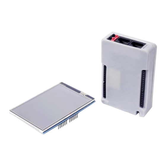
ICOP Technology Inc. 1.1 Introduction The QEC-RXXUN01 is an EtherCAT Slave module that supports both 2.4" and 3.5" TFT LCDs with touch functionality. It distinguishes itself as a comprehensive EtherCAT Slave module solution for on-machine displays in field-bus systems, providing a wide range of signal and power connections to ensure easy integration with commonly used display sizes and types. -
Page 8: Specifications
Supported LCM items: LCM Driver IC ID LCM Driver IC Resolution 0x4747 HX8347-D 240 X 320 0x9595 HX8347-I(T) 240 X 320 0x9341 ILI9341 240 X 320 0x9486 ILI9486 320 X 480 0x9488 ILI9488 320 X 480 QEC-RXXUN01 User Manual Ver.1 November, 2023... -
Page 9: Dimension
ICOP Technology Inc. 1.3 Dimension (Unit: mm) QEC-RXXUN01 User Manual Ver.1 November, 2023... -
Page 10: Ordering Information
Above is the standard Part Number, please contact our sales if you need to order other part number. QEC-R00UN01-N: EtherCAT Slave LCD Module ⚫ QEC-R00UN01-C: EtherCAT Slave LCD Module (board with coating) ⚫ QEC-R11UN01-N: EtherCAT Slave LCD Module /PoE ⚫ QEC-RXXUN01 User Manual Ver.1 November, 2023... -
Page 11: 2 Hardware System
ICOP Technology Inc. Hardware System 2.1 General Technical Data 2.2 Connector Summary 2.3 Wiring to the Connector QEC-RXXUN01 User Manual Ver.1 November, 2023... -
Page 12: General Technical Data
Power and Connection Status LEDs External Status LEDs A0 – A6/GND Signal 2.54mm 8-pin Female 8-pin VCC3/VCC/GND Signal 2.54mm 8-pin Female 8-pin TX/RX/PWM Signal 2.54mm 8-pin Female 8-pin I2C/PWM Signal 2.54mm 10-pin Female 10-pin QEC-RXXUN01 User Manual Ver.1 November, 2023... -
Page 13: Ethercat Interface
L4, L5, L7, L8 pins are option, for RJ45 Power IN/OUT. 2.2.2 Power Connector Trace width with 2mm. Pin # Signal Name Pin # Signal Name Vs- (GND) Vp- (GND) Power Input voltage +19 to +50VDC Power Input (Typ. +24VDC). QEC-RXXUN01 User Manual Ver.1 November, 2023... -
Page 14: Power And Connection Status Leds
Voltage < 19V and Voltage < 17V Red LED On Voltage >= 50V and Voltage <= 17V Power input is 24V (typical). The LED status provide high/low voltage warning. Vs power status will be displayed first. QEC-RXXUN01 User Manual Ver.1 November, 2023... -
Page 15: A0-A6/Gnd
ICOP Technology Inc. 2.2.4 A0-A6/GND PH1*8F (2.54) – 3.2. Pin # Signal Name 2.2.5 VCC3/VCC/GND PH1*8F (2.54) – 3.2. Pin # Signal Name VCC3 reset-a VCC3 QEC-RXXUN01 User Manual Ver.1 November, 2023... -
Page 16: Tx/Rx/Pwm
ICOP Technology Inc. 2.2.6 TX/RX/PWM PH1*8F (2.54) – 3.2. Pin # Signal Name 2.2.7 I2C/PWM PH1*10F (2.54) - 3.2 Pin # Signal Name I2C1_SDA I2C1_SCL QEC-RXXUN01 User Manual Ver.1 November, 2023... -
Page 17: Wiring To The Connector
2.3 Wiring to the Connector 2.3.1 Connecting the wire to the connector Insulated Terminals Dimensions (mm) Position Ø D1 Ø d1 Ø D2 CN 0.5-6 CN 0.5-8 CN 0.5-10 10.0 2.3.2 Removing the wire from the connector QEC-RXXUN01 User Manual Ver.1 November, 2023... -
Page 18: 3 Hardware Installation
ICOP Technology Inc. Hardware Installation 3.1 LCD Information 3.2 LCD Installation QEC-RXXUN01 User Manual Ver.1 November, 2023... -
Page 19: Lcd Information
ICOP Technology Inc. This section describes how to install 2.4” TFT LCD to QEC-RXXUN01 device. Please turn OFF the power supply before you mount LCD to QEC-RXXUN01. 3.1 LCD Information 2.4” TFT LCD Module is one of the most common RGB color display modules. - Page 20 DO pin the data output pin of the SPI communication system. SD_DI The DI pin is the data input pin of the SPI communication system. SD_SS The SS pin will enable the SPI communication through the signal of the SS pin. QEC-RXXUN01 User Manual Ver.1 November, 2023...
-
Page 21: Lcd Installation
ICOP Technology Inc. 3.2 LCD Installation The connection as below. QEC-RXXUN01 User Manual Ver.1 November, 2023... - Page 22 LCD_RD LCD_D7 LCD_D0 LCD_D1 SD_CS SD_DI VCC3 SD_DO reset-a RESET SD_SCK VCC3 I2C1_SDA I2C1_SCL -: connected but no signal; NC: disconnection. After connection, your QEC-RXXUN01 with 2.4” TFT LCD will be like below picture. QEC-RXXUN01 User Manual Ver.1 November, 2023...
-
Page 23: 4 Slave Information
ICOP Technology Inc. Slave Information 4.1 ESI (EtherCAT Slave Information) file 4.2 Object Dictionary QEC-RXXUN01 User Manual Ver.1 November, 2023... -
Page 24: Esi (Ethercat Slave Information) File
EtherCAT Master software. The latest version of the XML device description file can be downloaded from the QEC website. https://www.qec.tw/ 4.2 Object Dictionary The object dictionary defined here shall be used complementary with ETG.5001 and ETG.1000. Device Profile: 5001 Modul Profile: 0 Modular Device Profile QEC-RXXUN01 User Manual Ver.1 November, 2023... -
Page 25: Standard Objects (0X1000-0X1Fff)
QEC-R00UN01 LCD Module with PoE QEC-R11UN01 Index 1009 Hardware version Index Name Data type Flags Default 1009 Hardware version STRING DM449A Index 100A Index Name Data type Flags Default 100A Software version STRING 1.00 QEC-RXXUN01 User Manual Ver.1 November, 2023... - Page 26 Index 1A00 TouchScreenStatus process data mapping Index Name Data type Flags Default TouchScreenStatus process 1A00:0 UINT8 > 3 < data mapping 1A00:01 SubIndex 001 UINT32 0x6000:01, 16 1A00:02 SubIndex 002 UINT32 0x6000:02, 16 1A00:03 SubIndex 003 UINT32 0x6000:03, 16 QEC-RXXUN01 User Manual Ver.1 November, 2023...
- Page 27 0x0000 (0) 1C33:09 Delay Time UINT32 0x00000000 (0) 1C33:0A Sync0 Cycle Time UINT32 0x00000000 (0) 1C33:0B SM-Event Missed UINT16 0x0000 (0) 1C33:0C Cycle Time Too Small UINT16 0x0032 (50) 1C33:20 Sync Error BOOL TRUE QEC-RXXUN01 User Manual Ver.1 November, 2023...
-
Page 28: Manufacturer Objects (0X5000-0X5Fff)
Index 0x5010 LCD 2p4 Function Read Index Name Data type Flags Default 5010:0 LCD_2p4_Function_Read UINT8 RO P > 4 < 5010:01 ReadID UINT16 0x9341 (37697) 5010:02 Width UINT16 5010:03 Height UINT16 5010:04 GetRotation UINT8 0x00 (0) QEC-RXXUN01 User Manual Ver.1 November, 2023... - Page 29 Index 0x5012 LCD 2p4 Text Function Index Name Data type Flags Default 5012:0 LCD_2p4_Text_Function UINT8 RO P > 5 < 5012:01 Cursor UINT32 5012:02 Color UINT32 5012:03 Size UINT16 5012:04 Wrap UINT8 0x01 (1) 5012:05 Println STRING QEC-RXXUN01 User Manual Ver.1 November, 2023...
- Page 30 ICOP Technology Inc. Index 0x5013 Touch Screen Index Name Data type Flags Default 5013 TouchScreen STRING Index 0x5014 Parameter Index Name Data type Flags Default 5014 Parameter STRING QEC-RXXUN01 User Manual Ver.1 November, 2023...
-
Page 31: Especial Objects
Maximum number of modules UINT16 0x0000 (0) If this is your first time running EtherCAT and using a QEC-M master, we recommend that you read Set up the QEC-M-043T for 86Duino to get your project started. QEC-RXXUN01 User Manual Ver.1 November, 2023... -
Page 32: Warranty
All Trademarks appearing in this manuscript are registered trademark of their respective owners. All Specifications are subject to change without notice. © ICOP Technology Inc. 2023 QEC-RXXUN01 User Manual Ver.1 November, 2023...
Need help?
Do you have a question about the QEC-RXXUN01 and is the answer not in the manual?
Questions and answers