
Subscribe to Our Youtube Channel
Related Manuals for ICOP Technology QEC-RXXMV3S


Summary of Contents for ICOP Technology QEC-RXXMV3S
- Page 1 ICOP Technology Inc. User Manual QEC-RXXMV3S EtherCAT Slave Pulse Output module Up to 3-axis Pulse Output Control (Revision 1.0) QEC-RXXMV3S User Manual Ver.1.0 August, 2024...
- Page 2 ICOP Technology Inc. REVISION DATE VERSION DESCRIPTION 2024/8/29 Version 1.0 New Release. QEC-RXXMV3S User Manual Ver.1.0 August, 2024...
- Page 3 No part of this manual may be reproduced, copied, translated or transmitted, in whole or in part, in any form or by any means without the prior written permission of ICOP Technology Inc. ©Copyright 2024 ICOP Technology Inc. Ver.1.0 August, 2024 TRADEMARKS ACKNOWLEDGMENT ICOP®...
- Page 4 WARNING! DO NOT ATTEMPT TO OPEN OR TO DISASSEMBLE THE CHASSIS (ENCASING) OF THIS PRODUCT. PLEASE CONTACT YOUR DEALER FOR SERVICING FROM QUALIFIED TECHNICIAN. QEC-RXXMV3S User Manual Ver.1.0 August, 2024...
- Page 5 2.3.7 Differential Encoder (A/B/Z) Wiring ................28 Ch. 3 Hardware Installation ....................29 3.1 DIN-Rail installation ..................... 30 3.2 Removing QEC-RXXMV3S Unit ................31 Ch. 4 EtherCAT Communication ..................32 4.1 EtherCAT Basics ....................33 4.2 EtherCAT Cabling ....................33 4.3 EtherCAT State Machine ..................
- Page 6 6.2.2 RxPDO Mapping Objects ....................61 6.2.3 TxPDO Mapping Objects ....................66 6.2.4 Sync Manager Objects ....................72 6.2.5 Manufacturer Objects ....................75 6.2.6 Motor Objects ........................ 76 6.2.7 Especial Objects (0x6000-0xFFFF) ................102 Warranty ........................... 123 QEC-RXXMV3S User Manual Ver.1.0 August, 2024...
- Page 7 General Information 1.1 Introduction 1.2 Specifications 1.3 Dimension 1.4 Mounting Instruction 1.5 Ordering Information QEC-RXXMV3S User Manual Ver.1.0 August, 2024...
- Page 8 QEC-RXXMV3S a reliable and precise solution for high-performance industrial applications. The QEC-RXXMV3S series has a compact size of 107.45 x 77.39 x 34 mm, making it very convenient for system installation via Din-Rail mounting. It operates within a temperature range of -20°C to +70°C and is equipped with two network ports for EtherCAT network...
- Page 9 PWR, RUN, LINK, ERROR, Alarm, Home, Motor Certifications CE, FCC, VCCI Environment Operating Temperature -20 to +70 °C Hardware Dimension 107.45 x 66 x 30mm (Without DIN-Rail) Weight 370 g Installation DIN rail Internal Monitoring Temperature, Voltage, Current, Startup time QEC-RXXMV3S User Manual Ver.1.0 August, 2024...
- Page 10 ICOP Technology Inc. 1.3 Dimension (Unit: mm) QEC-RXXMV3S User Manual Ver.1.0 August, 2024...
- Page 11 ICOP Technology Inc. 1.4 Mounting Instruction QEC-RXXMV series is an easy-install design to help you set-up your modules easily. Please refer to Ch.3.1 DIN-Rail installation. DIN-Rill QEC-RXXMV3S User Manual Ver.1.0 August, 2024...
- Page 12 ⚫ QEC-R00MV3S-C: EtherCAT Slave 3 axis Pulse Output Module (board with coating). ⚫ QEC-R11MV3S-N: EtherCAT Slave 3 axis Pulse Output Module/PoE. ⚫ QEC-R11MV3S-C: EtherCAT Slave 3 axis Pulse Output Module/PoE (board with coating). ⚫ QEC-RXXMV3S User Manual Ver.1.0 August, 2024...
- Page 13 ICOP Technology Inc. Hardware System 2.1 General Technical Data 2.2 Connector Summary 2.3 Wiring to the Connector QEC-RXXMV3S User Manual Ver.1.0 August, 2024...
- Page 14 ICOP Technology Inc. 2.1 General Technical Data QEC-RXXMV3S User Manual Ver.1.0 August, 2024...
- Page 15 Power Socket. 6-pin Power and Connection Status LEDs Status LEDs. Drive Status LEDs Status LEDs. M1-axis Connector Drive M1 axis. 16-pin M2-axis Connector Drive M2 axis. 16-pin M3-axis Connector Drive M3 axis. 16-pin DIN-Rail QEC-RXXMV3S User Manual Ver.1.0 August, 2024...
- Page 16 Pin # Signal Name LAN2_TX+ LAN2_TX- LAN2_RX+ LAN2_RX- VS- (GND) VP- (GND) PoE LAN with the Red Housing; Regular LAN with Black Housing. L4, L5, L7, L8 pins are option, for RJ45 Power IN/OUT. QEC-RXXMV3S User Manual Ver.1.0 August, 2024...
- Page 17 4-pins Power Input/Output & 2-pins FGND. Vs for system power; Vp for peripheral power and backup power. Pin # Signal Name Pin # Signal Name Vs- (GND) Vp- (GND) Power Input voltage +19 to +50VDC Power Input (Typ. +24VDC) QEC-RXXMV3S User Manual Ver.1.0 August, 2024...
- Page 18 Orange LED (Green + Red) will continuously flash Orange LED On Voltage > 50V or < 12V (at 0.3-second intervals) until the Vs and Vp voltages are correct. Vs power status will be displayed first. QEC-RXXMV3S User Manual Ver.1.0 August, 2024...
- Page 19 1 Long Light 1 short flash microchip internal SRAM failed. 2 short flashes APP software CHECKSUM failed. 2 Long Lights Not yet defined. Note: If you encounter any of the above abnormal states, please contact us. QEC-RXXMV3S User Manual Ver.1.0 August, 2024...
- Page 20 The device is in state Safe-Operation The device is in state Operation No error Blinking Invalid Configuration Single Flash Local Error Process Data Watchdog Timeout Double Flash EtherCAT Watchdog Timeout The device is in state Error QEC-RXXMV3S User Manual Ver.1.0 August, 2024...
- Page 21 ICOP Technology Inc. 2.2.4 Drive Status LEDs Home, SVON, Alarm Status LEDs. Notation Color Description Home Orange Machine Home signal. SVON Orange Machine Servo-ON (SVON) signal. Alarm Orange Machine Alarm signal. QEC-RXXMV3S User Manual Ver.1.0 August, 2024...
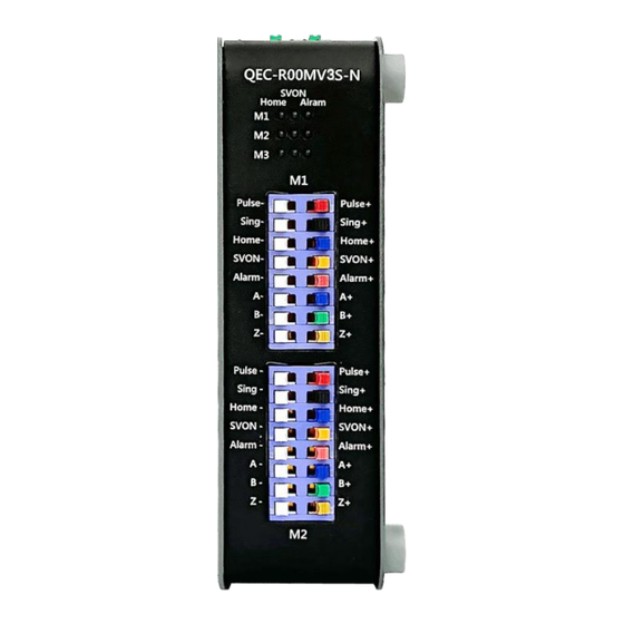
- Page 22 Homing signal (positive) Home+ Blue Input Homing signal (negative) Home- White Input Servo-on signal (positive) SVON+ Orange Output Servo-on signal (negative) SVON- White Output Alarm signal (positive) Alarm+ Input Alarm signal (negative) Alarm- White Input QEC-RXXMV3S User Manual Ver.1.0 August, 2024...
- Page 23 Differential Encoder A phase (negative, 5V) Green Input Differential Encoder B phase (positive, 5V) White Input Differential Encoder B phase (negative, 5V) Brown Input Differential Encoder Z phase (positive, 5V) White Input Differential Encoder Z phase (negative, 5V) QEC-RXXMV3S User Manual Ver.1.0 August, 2024...
- Page 24 Homing signal (positive) Home+ Blue Input Homing signal (negative) Home- White Input Servo-on signal (positive) SVON+ Orange Output Servo-on signal (negative) SVON- White Output Alarm signal (positive) Alarm+ Input Alarm signal (negative) Alarm- White Input QEC-RXXMV3S User Manual Ver.1.0 August, 2024...
- Page 25 Differential Encoder A phase (negative, 5V) Green Input Differential Encoder B phase (positive, 5V) White Input Differential Encoder B phase (negative, 5V) Brown Input Differential Encoder Z phase (positive, 5V) White Input Differential Encoder Z phase (negative, 5V) QEC-RXXMV3S User Manual Ver.1.0 August, 2024...
- Page 26 Homing signal (positive) Home+ Blue Input Homing signal (negative) Home- White Input Servo-on signal (positive) SVON+ Orange Output Servo-on signal (negative) SVON- White Output Alarm signal (positive) Alarm+ Input Alarm signal (negative) Alarm- White Input QEC-RXXMV3S User Manual Ver.1.0 August, 2024...
- Page 27 Differential Encoder A phase (negative, 5V) Green Input Differential Encoder B phase (positive, 5V) White Input Differential Encoder B phase (negative, 5V) Brown Input Differential Encoder Z phase (positive, 5V) White Input Differential Encoder Z phase (negative, 5V) QEC-RXXMV3S User Manual Ver.1.0 August, 2024...
- Page 28 ICOP Technology Inc. 2.2.8 DIN-Rail installation Please refer to Ch.3.1 DIN-Rail installation. QEC-RXXMV3S User Manual Ver.1.0 August, 2024...
- Page 29 2.3 Wiring to the Connector 2.3.1 Connecting the wire to the connector Insulated Terminals Dimensions (mm) Position Ø D1 Ø d1 Ø D2 CN 0.5-6 CN 0.5-8 CN 0.5-10 10.0 2.3.2 Removing the wire from the connector QEC-RXXMV3S User Manual Ver.1.0 August, 2024...
- Page 30 Pulse +/- signal application wiring: Sing +/- signal application wiring: The diagram shows the correct wiring for a 5V differential signal input for the QEC-RXXMV3S. The connection includes a 330Ω resistor to ensure proper signal conditioning. The differential signals are correctly routed to the input terminals of the device.
- Page 31 Digital Input Digital Input channels Input type Sink Voltage level +19 to +50VDC Isolation Voltage Protection 2500 Vrms Application wiring: Circuit examples for Home of M1. The same principles apply to M2 and M3. QEC-RXXMV3S User Manual Ver.1.0 August, 2024...
- Page 32 Digital Output Digital Output channels Output type Sink Voltage level +19 to +50VDC Isolation Voltage Protection 2500 Vrms Application wiring: Circuit examples for SVON of M1. The same principles apply to M2 and M3. QEC-RXXMV3S User Manual Ver.1.0 August, 2024...
- Page 33 Digital Input Digital Input channels Input type Sink Voltage level +19 to +50VDC Isolation Voltage Protection 2500 Vrms Application Wiring: Circuit examples for Alarm of M1. The same principles apply to M2 and M3. QEC-RXXMV3S User Manual Ver.1.0 August, 2024...
- Page 34 Circuit examples for Encoder of M1. The same principles apply to M2 and M3. The encoder in the QEC-RXXMV3S can read various signals, including A, B, and Z. It's capable of interpreting pulse signals and determining motor rotation direction, CW (clockwise) or CCW (counter clockwise).
- Page 35 ICOP Technology Inc. Hardware Installation 3.1 DIN-Rail installation 3.2 Removing QEC-RXXM3S Unit QEC-RXXMV3S User Manual Ver.1.0 August, 2024...
- Page 36 ICOP Technology Inc. 3.1 DIN-Rail installation Slide in the QEC-RXXMV3S on the hookup guides and press the QEC-RXXMV3S with a certain amount of force against the DIN track until the DIN Track mounting hook lock into place. When you mount the QEC-RXXMV3S, releasing the DIN track mounting hook on the QEC-RXXMV3S is unnecessary.
- Page 37 ICOP Technology Inc. 3.2 Removing QEC-RXXMV3S Unit Use a flat-blade screwdriver to remove the DIN Track mounting hook on the unit. Pull down and out the flat-blade screwdriver with force against the DIN track until you hear the DIN Track remove the hook.
- Page 38 ICOP Technology Inc. EtherCAT Communication 4.1 EtherCAT Basics 4.2 EtherCAT Cabling 4.3 EtherCAT State Machine 4.4 Process Data Object 4.5 CAN application protocol over EtherCAT 4.6 Synchronization Modes QEC-RXXMV3S User Manual Ver.1.0 August, 2024...
- Page 39 EtherCAT uses 4 wires for signal transfer. The pin assignment is compatible with the Ethernet standard (ISO/IEC 8802-3). Color of conductor Signal Description Yellow Transmission Data+ Orange Transmission Data- White RD + Receiver Data+ Blue RD - Receiver Data- QEC-RXXMV3S User Manual Ver.1.0 August, 2024...
- Page 40 The regular state of each EtherCAT slave after bootup is the OP state. Init After switch-on the EtherCAT slave in the Init state. No mailbox or process data communication is possible. The EtherCAT master initializes sync manager channels 0 and 1 for mailbox communication. QEC-RXXMV3S User Manual Ver.1.0 August, 2024...
- Page 41 In the Boot state the slave firmware can be updated. The Boot state can only be reached via the Init state. In the Boot state mailbox communication via the file access over EtherCAT (FoE) protocol is possible, but no other mailbox communication and no process data communication QEC-RXXMV3S User Manual Ver.1.0 August, 2024...
- Page 42 Output PDO from the packet by reading object 0x1C32.6. 2. ECAT_Application: Execute the user command read from the packet. Taking QEC-RXXMV3S (CiA-402 mode) as an example, QEC-RXXMV3S will start to control the 3-axis pulse output to rotate to the position specified by the user in ECAT_Application. 3. PDO_InputMapping: Upload read-only parameters (current motor position and speed, Digital Input Level, ADC reading value) to Input PDO.
- Page 43 0x1620 0x707A 0x00 INT32 0x1620 0x70FF 0x00 INT32 0x1620 0x7060 0x00 INT8 Application Object List: Object Name 0x6040 0x00 Control Word 0x607A 0x00 Target Position 0x60FF 0x00 Target velocity 0x6060 0x00 Mode of Operation QEC-RXXMV3S User Manual Ver.1.0 August, 2024...
- Page 44 Position actual value 0x1A20 0x706C 0x00 INT32 Velocity Actual Value 0x1A20 0x70E4 0x01 Additional position encoder value 0x1A20 0x70FD 0x00 UINT32 Digital inputs 0x1A20 0x7061 0x00 INT8 Modes of operation display 0x1A20 0x5024 0x03 ENC Status QEC-RXXMV3S User Manual Ver.1.0 August, 2024...
- Page 45 1C12h is object to assign RxPDO and can assign one object among RxPDO 1600, 1610, or 1620 Objects. ⚫ 1C13h is object to assign TxPDO and can assign one object among TxPDO 1A00, 1A10, or 1A20 Objects. ⚫ QEC-RXXMV3S User Manual Ver.1.0 August, 2024...
- Page 46 ICOP Technology Inc. 4.4.3 PDO Operation Process For G-code Mode Operation Process: QEC-RXXMV3S User Manual Ver.1.0 August, 2024...
- Page 47 ICOP Technology Inc. QEC-RXXMV3S User Manual Ver.1.0 August, 2024...
- Page 48 ICOP Technology Inc. QEC-RXXMV3S User Manual Ver.1.0 August, 2024...
- Page 49 (read-only) or variable parameters required for operation, diagnostics, or commissioning. CoE parameters are arranged in a table hierarchy. In principle, the user has read access via the fieldbus. QEC-RXXMV3S supports CAN application protocol over EtherCAT (CoE). EtherCAT Slave structure is as follows. QEC-RXXMV3S User Manual...
- Page 50 ICOP Technology Inc. 4.6 Synchronization Modes Synchronization modes provided by QEC-RXXMV3S are as follows. 4.6.1 Free Run In this mode, the EtherCAT slave device operates independently of the EtherCAT master's timing. The slave does not synchronize its operations with the master's clock or any other synchronization signals in the EtherCAT network.
- Page 51 This mode is essential for complex motion control tasks and synchronized operations across multiple devices in an automated system. EtherCAT: Illustration of Distributed Clock (DC). (Source of information: http://www.ethercat.org/) QEC-RXXMV3S User Manual Ver.1.0 August, 2024...
- Page 52 ICOP Technology Inc. Getting Started 5.1 Introduction 5.2 TwinCAT (PP Mode) 5.3 86Duino Coding IDE (PP Mode) 5.4 86Duino Coding IDE (G-code Mode) QEC-RXXMV3S User Manual Ver.1.0 August, 2024...
- Page 53 When connecting PoE and non-PoE devices, make sure to disconnect Ethernet cables at pins 4, 5, 7, and 8 (e.g., when a PoE-supported QEC EtherCAT master connects with a third-party EtherCAT slave). QEC’s PoE power supply is up to 24V/3A. QEC-RXXMV3S User Manual Ver.1.0 August, 2024...
- Page 54 To facilitate this process, we will focus on one software tools: 86Duino IDE, which is compatible with the QEC Master Series. In the following pages, we will walk you through the steps for connecting your QEC-RXXMV3S and initiating your journey toward fully integrating this stepper motor driver into your projects.
- Page 55 Here, we'll guide you through the key steps to get your QEC-R11MV3S up and running with the 86Duino IDE. We will show you how to use the EtherCAT Master QEC-M-01P and the QEC-RXXMV3S Series. We will be operating CiA402 Cyclic synchronous position (CSP) mode.
- Page 56 After downloading, please unzip the downloaded zip file, no additional software installation is required, just double-click 86duino.exe to start the IDE. *Note: If Windows displays a warning, click Details once and then click the Continue Run button once. 86Duino Coding IDE 500+ looks like below. QEC-RXXMV3S User Manual Ver.1.0 August, 2024...
- Page 57 5. Select the correct board: In the IDE's menu, select Tools> Board > QEC-M-01 (or the QEC-M master model you use). 6. Select Port: In the IDE's menu, select Tools > Port and select the USB port to connect to the QEC-M master (in this case, COM4 (QEC)). QEC-RXXMV3S User Manual Ver.1.0 August, 2024...
- Page 58 EtherCAT communication protocol. We will use the Cyclic synchronous position (CSP) mode from the CiA402 standard. You can use 86EVA to check the QEC-RXXMV3S is in CiA402 mode. The Predefined PDO Assignment is set as the following table:...
- Page 59 Note: Once the code is written, click on the toolbar to compile, and to confirm that the compilation is complete and error-free, you can click to upload. The program will run when the upload is complete. QEC-RXXMV3S User Manual Ver.1.0 August, 2024...
- Page 60 5.3 86Duino Coding IDE (G-code Mode) In this section, we will show you how to use the EtherCAT Master QEC-M-01P and the QEC-RXXMV3S Series. We will be operating G-code mode. We use the same software and hardware with 5.2 86Duino Coding IDE (CSP Mode).
- Page 61 1000, after which the program pauses for 6 seconds to ensure the action is completed. Then, the X-axis returns to position 0 at a speed of 10000, and the program pauses for 1 second to ensure the action is completed. This process will continuously repeat. QEC-RXXMV3S User Manual Ver.1.0 August, 2024...
- Page 62 Note: Once the code is written, click on the toolbar to compile, and to confirm that the compilation is complete and error-free, you can click to upload. The program will run when the upload is complete. QEC-RXXMV3S User Manual Ver.1.0 August, 2024...
- Page 63 ICOP Technology Inc. Slave Information 6.1 ESI (EtherCAT Slave Information) file 6.2 Object Dictionary QEC-RXXMV3S User Manual Ver.1.0 August, 2024...
- Page 64 0x1000, 0x1001, 0x1008, 0x1009, 0x100a, 0x1010, 0x1011, 0x1018, 0x10F0, 0x10F1, 0x10F3, 0x1c00, 0x1c32, 0x1c33 Entries less or equal one 8Bit shall not overlap byte borders. Entries greater 8Bit shall always start at an exact word border. QEC-RXXMV3S User Manual Ver.1.0 August, 2024...
- Page 65 Pulse Output Module without PoE QEC-R00MV3S Pulse Output Module with PoE QEC-R11MV3S Index 1009 Hardware version Index Name Data type Flags Default Depends on the version of the 1009 Hardware version STRING product you have. QEC-RXXMV3S User Manual Ver.1.0 August, 2024...
- Page 66 0x00000001 (1) 10F1:02 Sync Error Counter Limit UINT32 0x0004 (4) Index 10F8 Timestamp Object Index Name Data type Flags Default 10F8 Timestamp Object UINT64 RW P 9E 04 CA F3 20 00 00 00 QEC-RXXMV3S User Manual Ver.1.0 August, 2024...
- Page 67 Flags Default Description 1602:0 X Axis RxPdoMapping2 UINT8 > 2 < RX PDO Mapping for CSV. 1602:01 SubIndex 001 UINT32 0x6040:00, 16 Map control word. 1602:02 SubIndex 002 UINT32 0x60FF:00, 32 Map target velocity. QEC-RXXMV3S User Manual Ver.1.0 August, 2024...
- Page 68 SubIndex 001 UINT32 0x6040:00, 16 Map control word. 1604:02 SubIndex 002 UINT32 0x607A:00, 32 Map target position. 1604:03 SubIndex 003 UINT32 0x6081:00, 32 Map profile velocity. 1604:04 SubIndex 004 UINT32 0x6083:00, 32 Map profile acceleration. QEC-RXXMV3S User Manual Ver.1.0 August, 2024...
- Page 69 SubIndex 001 UINT32 0x6840:00, 16 Map control word. 1614:02 SubIndex 002 UINT32 0x687A:00, 32 Map target position. 1614:03 SubIndex 003 UINT32 0x6881:00, 32 Map profile velocity. 1614:04 SubIndex 004 UINT32 0x6883:00, 32 Map profile acceleration. QEC-RXXMV3S User Manual Ver.1.0 August, 2024...
- Page 70 SubIndex 001 UINT32 0x7040:00, 16 Map control word. 1624:02 SubIndex 002 UINT32 0x707A:00, 32 Map target position. 1624:03 SubIndex 003 UINT32 0x7081:00, 32 Map profile velocity. 1624:04 SubIndex 004 UINT32 0x7083:00, 32 Map profile acceleration. QEC-RXXMV3S User Manual Ver.1.0 August, 2024...
- Page 71 Index 1632 G code RX PDO Mapping2 Index Name Data type Flags Default Description 1632:0 G code RxPdoMapping2 UINT8 > 1 < For RX PDO mapping number is less than 3. 1632:01 SubIndex 001 UINT32 0x0000:00, 0 Empty QEC-RXXMV3S User Manual Ver.1.0 August, 2024...
- Page 72 UINT32 0x6064:00, 32 Map actual position. 1A01:03 SubIndex 003 UINT32 0x60E4:01, 32 Map additional position actual value. 1A01:04 SubIndex 004 UINT32 0x60FD:00, 32 Map digital inputs. 1A01:05 SubIndex 005 UINT32 0x5024:01, 8 ENC status. QEC-RXXMV3S User Manual Ver.1.0 August, 2024...
- Page 73 UINT32 0x606C:00, 32 Map actual velocity. 1A02:04 SubIndex 004 UINT32 0x60E4:01, 32 Map additional position actual value. 1A02:05 SubIndex 005 UINT32 0x60FD:00, 32 Map digital inputs. 1A02:06 SubIndex 006 UINT32 0x5024:01, 8 ENC status. QEC-RXXMV3S User Manual Ver.1.0 August, 2024...
- Page 74 UINT32 0x6864:00, 32 Map actual position. 1A11:03 SubIndex 003 UINT32 0x68E4:01, 32 Map additional position actual value. 1A11:04 SubIndex 004 UINT32 0x68FD:00, 32 Map digital inputs. 1A11:05 SubIndex 005 UINT32 0x5024:02, 8 ENC status. QEC-RXXMV3S User Manual Ver.1.0 August, 2024...
- Page 75 0x70E4:01, 32 Map additional position actual value. 1A20:05 SubIndex 005 UINT32 0x70FD:00, 32 Map digital inputs. 1A20:06 SubIndex 006 UINT32 0x7061:00, 8 Map mode of operation display. 1A20:07 SubIndex 007 UINT32 0x5024:03, 8 ENC status. QEC-RXXMV3S User Manual Ver.1.0 August, 2024...
- Page 76 UINT32 0x7064:00, 32 Map actual position. 1A24:03 SubIndex 003 UINT32 0x70E4:01, 32 Map additional position actual value. 1A24:04 SubIndex 004 UINT32 0x70FD:00, 32 Map digital inputs. 1A24:05 SubIndex 005 UINT32 0x5024:03, 8 ENC status. QEC-RXXMV3S User Manual Ver.1.0 August, 2024...
- Page 77 Index 1A32 G code TX PDO Mapping2 Index Name Data type Flags Default Description 1A32:0 G code TxPdoMapping2 UINT8 > 1 < For TX PDO mapping number is less than 3. 1A32:01 SubIndex 001 UINT32 0x0000:00, 0 Empty QEC-RXXMV3S User Manual Ver.1.0 August, 2024...
- Page 78 TX PDO Assign UINT8 > 3 < CiA-402 Mode G-code Mode 0x1C13:01 SubIndex 01 UINT16 RO, wr_preop 0x1A00 0x1A30 0x1C13:02 SubIndex 02 UINT16 RO, wr_preop 0x1A10 0x1A31 0x1C13:03 SubIndex 03 UINT16 RO, wr_preop 0x1A20 0x1A32 QEC-RXXMV3S User Manual Ver.1.0 August, 2024...
- Page 79 0x0000 (0) 1C32:0C Cycle Time Too Small UINT16 0x0000 (0) 1C32:0D Shift Time Too Short 1C32:0E SubIndex 014 1C32:0F SubIndex 015 1C32:10 SubIndex 016 1C32:11 SubIndex 017 1C32:12 SubIndex 018 1C32:20 Sync Error BOOL FALSE QEC-RXXMV3S User Manual Ver.1.0 August, 2024...
- Page 80 0x0000 (0) 1C33:0C Cycle Time Too Small UINT32 0x0000 (0) 1C33:0D Shift Time Too Short 1C33:0E SubIndex 014 1C33:0F SubIndex 015 1C33:10 SubIndex 016 1C33:11 SubIndex 017 1C33:12 SubIndex 018 1C33:20 Sync Error BOOL FALSE QEC-RXXMV3S User Manual Ver.1.0 August, 2024...
- Page 81 5006:02 OrderNo STRING(8) 78787878787878 Order No 5006:03 InvNo STRING(11) 78787878787878787878 Inv No 5006:04 DelyDate STRING(4) 787878 Dely Date 5007:0 MTBF > 2 < MTBF 5007:01 WorkingHours INT32 Working Hours 5007:02 BootTimes INT32 Boot Times QEC-RXXMV3S User Manual Ver.1.0 August, 2024...
- Page 82 1.8° step angle, Motor Pulse should be set to 360/1.8*16 = 3200. Index Name Data type Flags Default 5011:0 Motor Pulse UINT8 > 3 < 5011:01 UINT32 RO, wr_preop 0x00000C80 (3200) 5011:02 UINT32 RO, wr_preop 0x00000C80 (3200) 5011:03 UINT32 RO, wr_preop 0x00000C80 (3200) QEC-RXXMV3S User Manual Ver.1.0 August, 2024...
- Page 83 0x708C 0x50DC 0x687E 0x5011 Index 0x5013 Set Actual POS Index Name Data type Flags Default 5013:0 Set Actual POS UINT16 0x0000 (0) 5013:01 INT32 0x0000 (0) 5013:02 INT32 0x0000 (0) 5013:03 INT32 0x0000 (0) QEC-RXXMV3S User Manual Ver.1.0 August, 2024...
- Page 84 ENC Mode UINT8 > 3 < 5020:01 ENC_1 UINT8 0x07 (7) 5020:02 ENC_2 UINT8 0x07 (7) 5020:03 ENC_3 UINT8 0x07 (7) Input signal waveforms: Mode Code MODE_STEP_DIR MODE_CWCCW MODE_AB_PHASE MODE_STEP_DIR_x2 MODE_CWCCW_x2 MODE_AB_PHASE_x2 MODE_AB_PHASE_x2 Any other QEC-RXXMV3S User Manual Ver.1.0 August, 2024...
- Page 85 ICOP Technology Inc. MODE_STEP_DIR MODE_CWCCW QEC-RXXMV3S User Manual Ver.1.0 August, 2024...
- Page 86 ICOP Technology Inc. MODE_AB_PHASE MODE_STEP_DIR_x2 QEC-RXXMV3S User Manual Ver.1.0 August, 2024...
- Page 87 ICOP Technology Inc. MODE_CWCCW_x2 MODE_AB_PHASE_x2 QEC-RXXMV3S User Manual Ver.1.0 August, 2024...
- Page 88 ENC Index Reset Pol Z Pol B Pol A Index Name Data type Flags Default 5022:0 ENC Control Byte UINT8 > 3 < 5022:01 ENC_1 UINT8 0x07 5022:02 ENC_2 UINT8 0x07 5022:03 ENC_3 UINT8 0x07 QEC-RXXMV3S User Manual Ver.1.0 August, 2024...
- Page 89 When the encoder value decrease to 0, then back to max value, PCNT-UV will be set to 1. [6 – 2] IDX-Reset Reserved PCNT-OV PCNT-UV Index Name Data type Flags Default 5024:0 ENC Status UINT8 > 3 < 5024:01 ENC_1 UINT8 5024:02 ENC_2 UINT8 5024:03 ENC_3 UINT8 QEC-RXXMV3S User Manual Ver.1.0 August, 2024...
- Page 90 Writing object 0x5025 would set encoder value to writing value. Additional position encoder value (0x60E4/0x68E4/ 0x70E4) would be updated to the same value. Index Name Data type Flags Default 5025:0 ENC Write UINT8 > 3 < 5025:01 ENC_1 INT32 5025:02 ENC_2 INT32 5025:03 ENC_3 INT32 QEC-RXXMV3S User Manual Ver.1.0 August, 2024...
- Page 91 0x5031.1: Order number of X-axis; 0x5031.2: Order number of Y-axis; 0x5031.3: Order number of Z-axis. Index Name Data type Flags Default 5031:0 Home Priority 5031:1 UINT8 0x03 5031:2 UINT8 0x02 5031:3 UINT8 0x01 QEC-RXXMV3S User Manual Ver.1.0 August, 2024...
- Page 92 Read/Write work offset of G55. 0x50C2.1: G55 X-axis coordinate. 0x50C2.2: G55 Y-axis coordinate. 0x50C2.3: G55 Z-axis coordinate. Index Name Data type Flags Default 50C2:0 G55_WorkOffset 50C2:01 REAL64 50C2:02 REAL64 50C2:03 REAL64 QEC-RXXMV3S User Manual Ver.1.0 August, 2024...
- Page 93 Read/Write work offset of G57. 0x50C4.1: G57 X-axis coordinate. 0x50C4.2: G57 Y-axis coordinate. 0x50C4.3: G57 Z-axis coordinate. Index Name Data type Flags Default 50C4:0 G57_WorkOffset 50C4:01 REAL64 50C4:02 REAL64 50C4:03 REAL64 QEC-RXXMV3S User Manual Ver.1.0 August, 2024...
- Page 94 Read/Write work offset of G59. 0x50C6.1: G59 X-axis coordinate. 0x50C6.2: G59 Y-axis coordinate. 0x50C6.3: G59 Z-axis coordinate. Index Name Data type Flags Default 50C6:0 G59_WorkOffset 50C6:01 REAL64 50C6:02 REAL64 50C6:03 REAL64 QEC-RXXMV3S User Manual Ver.1.0 August, 2024...
- Page 95 Changing the parity bit is equivalent to ending the transmission of the G code in that line. If Finish has not been executed, all previously transmitted strings will be discarded. String Segment Number: String Segment Number valid values are 1~14. QEC-RXXMV3S User Manual Ver.1.0 August, 2024...
- Page 96 0x50D1 0x50E0 0x0000 0x0000 0x0001 "G2 X2000000.0 Y2000000.0 " 0x0000 0x0001 "G2 X2000000.0 Y2000000.0 " 0x0001 0x0002 “Z100.0 I2000000.0 J0.0 F1" 0x0001 0x0002 “Z100.0 I2000000.0 J0.0 F1" 0x0002 0x0103 “536.0” 0x0002 0x0103 “536.0” 0x000F QEC-RXXMV3S User Manual Ver.1.0 August, 2024...
- Page 97 Min of X axis REAL64 50D5:02 Max of X axis REAL64 50D5:03 Min of Y axis REAL64 50D5:04 Max of Y axis REAL64 50D5:05 Min of Z axis REAL64 50D5:06 Max of Z axis REAL64 QEC-RXXMV3S User Manual Ver.1.0 August, 2024...
- Page 98 Object used to control the state of G Code Controller. The object type is UINT8, 0: Servo Off, 1: Servo On. When Servo Off, it cannot receive G code and cannot execute and return to Home. [7 – 4] Reserved Reserved Reserved Reserved Servo On/Off QEC-RXXMV3S User Manual Ver.1.0 August, 2024...
- Page 99 Object used to control the status of G Code Controller. The object type is UINT8. Changing the object to 4 will execute the software EmgStop. Restoring the object to 0 will not clear EmgStop. Clear EmgStop must be executed. [7 – 4] Reserved Reserved Emergency Stop Reserved Reserved QEC-RXXMV3S User Manual Ver.1.0 August, 2024...
- Page 100 G Code string also does not contain Feed-rate, G Code Controller will use the setting of the object Default Feedrate as Feed-rate. ; The unit of Default Feedrate is mm per minute, and the object data type is REAL64. QEC-RXXMV3S User Manual Ver.1.0 August, 2024...
- Page 101 If position limit is enabled, when motor reaches position limit(0x50D5), motor will stay at limit position. Setting object 0x50DD can enable/disable position limit: 0: disable position limit 1: enable position limit Index Name Data type Flags Default 50DD Enable Position Limit UINT8 0x01 (1) QEC-RXXMV3S User Manual Ver.1.0 August, 2024...
- Page 102 If the String Segment Counter is n (0~13), the String Segment Number must be n+1 for the Controller to receive the new string. String Segment Number Sting Segment Counter Action n + 1 Receive string to FIFO Any other Skip QEC-RXXMV3S User Manual Ver.1.0 August, 2024...
- Page 103 0x50D1 0x50E0 0x0000 0x0000 0x0001 "G2 X2000000.0 Y2000000.0 " 0x0000 0x0001 "G2 X2000000.0 Y2000000.0 " 0x0001 0x0011 "G1 X2000000.0 Y2000000.0 " 0x0001 0x0011 "G1 X2000000.0 Y2000000.0 " 0x0031 0x0112 “F1500.0” 0x0011 0x0112 “F1500.0” 0x001F QEC-RXXMV3S User Manual Ver.1.0 August, 2024...
- Page 104 EmgStop input pins. Status, the X in the table indicates that the object can be any value: Machine State EmgStop Input 0x50D9 0x50D8 0x50D7 Hardware Emergency Stop Software Emergency Stop Servo Off Servo On Homing QEC-RXXMV3S User Manual Ver.1.0 August, 2024...
- Page 105 REAL64 Index 0x50E3 Limit Inputs Display the pin status of XYZ three-axis Limit inputs. Index Name Data type Flags Default 50E3 Limit Inputs UINT8 [7 – 3] Reserved Z limit Y limit X limit QEC-RXXMV3S User Manual Ver.1.0 August, 2024...
- Page 106 Writing to the Device Profile (0x50FC) after booting will only change the address content of the SPI ROM where the Device Profile is stored. The results of Servo mode and reading the Device Profile will not change. QEC-RXXMV3S User Manual Ver.1.0 August, 2024...
- Page 107 REAL64 RO, wr_preop Index 0x50FF G Code command QEC-RXXMV3S supports receiving G-code via mailbox. Writing G-code string to object 0x50FF instructs QEC-RXXMV3S to execute this G-code when Servo-On. String length should be less than 63 characters. Index Name Data type...
- Page 108 Index 0x605B Shutdown option code Index Name Data type Flags Default 605B Shutdown option code INT16 0x0000 (0) Index 0x605E Fault reaction option code Index Name Data type Flags Default 605E Fault reaction option code INT16 0x0000 (0) QEC-RXXMV3S User Manual Ver.1.0 August, 2024...
- Page 109 Mandatory if CSP is supported. Index Name Data type Flags Default 607A Target position INT32 0x00000000 Index 0x607C Home offset Set Home Position. Index Name Data type Flags Default 607C Home offset INT32 0x00 QEC-RXXMV3S User Manual Ver.1.0 August, 2024...
- Page 110 Can’t be zero. Index Name Data type Flags Default 6081 Profile velocity UINT32 0x00000001 (1) Index 0x6083 Profile acceleration Can’t be zero. Index Name Data type Flags Default 6083 Profile acceleration UINT32 0x00000001 (1) QEC-RXXMV3S User Manual Ver.1.0 August, 2024...
- Page 111 Index 0x608B Velocity notation index Index Name Data type Flags Default 608B Velocity notation index INT8 Index 0x608C Velocity dimension index Save to EEPROM. Index Name Data type Flags Default 608C Velocity dimension index UINT8 0xA4 (164) QEC-RXXMV3S User Manual Ver.1.0 August, 2024...
- Page 112 With methods 19 and 20 (equivalent to methods 3 and 4), the left switching edge of the home switch is used as reference: With methods 21 and 22 (equivalent to methods 5 and 6), the right switching edge of the home switch is used as reference: QEC-RXXMV3S User Manual Ver.1.0 August, 2024...
- Page 113 Set Touch probe. Index Name Data type Flags Default 60B8 Touch probe function UINT16 0x0000 (0) Index 0x60B9 Touch probe status Index Name Data type Flags Default 60B9 Touch probe status UINT16 0x0000 (0) QEC-RXXMV3S User Manual Ver.1.0 August, 2024...
- Page 114 G-code is an object shared with CiA-402 mode and returns the encoder input of the M1 axis, M2 axis, and M3 axis. Index Name Data type Flags Default 60E4:0 Additional position encoder value 60E4:01 First additional position INT32 QEC-RXXMV3S User Manual Ver.1.0 August, 2024...
- Page 115 Name Data type Flags Default 60FF Target velocity INT32 Index 0x6502 Supported drive modes Bit7 (csp) and Bit8 (csv) are set. Index Name Data type Flags Default 6502 Supported drive modes UINT32 0x000001A1 (417) QEC-RXXMV3S User Manual Ver.1.0 August, 2024...
- Page 116 Position actual value INT32 Index 0x686C Velocity Actual Value Index Name Data type Flags Default 686C Velocity Actual Value INT32 Index 0x687A Target position Index Name Data type Flags Default 687A Target position INT32 QEC-RXXMV3S User Manual Ver.1.0 August, 2024...
- Page 117 Set Max motor speed. Index Name Data type Flags Default 6880 Max motor speed UINT32 0x0000012C (300) Index 0x6881 Profile velocity Can’t be zero. Index Name Data type Flags Default 6881 Profile velocity UINT32 0x00000001 (1) QEC-RXXMV3S User Manual Ver.1.0 August, 2024...
- Page 118 Speed for searching switch UINT32 0x00000001 (1) 6899:02 Speed for searching zero UINT32 0x00000001 (1) Index 0x689A Homing acceleration Can’t be zero. Index Name Data type Flags Default 689A Homing acceleration UINT32 0x00000001 (1) QEC-RXXMV3S User Manual Ver.1.0 August, 2024...
- Page 119 Touch probe position 1 negative value INT32 Index 0x68C2 Interpolation time period Index Name Data type Flags Default 68C2:0 Interpolation time period 68C2:01 Interpolation time period value UINT8 0x00 (0) 68C2:02 Interpolation time index UINT8 QEC-RXXMV3S User Manual Ver.1.0 August, 2024...
- Page 120 Mandatory if PV or CSV is supported. Index Name Data type Flags Default 68FF Target velocity INT32 Index 0x6D02 Supported drive modes Index Name Data type Flags Default 6D02 Supported drive modes UINT32 0x000001A1 (417) QEC-RXXMV3S User Manual Ver.1.0 August, 2024...
- Page 121 Modes of operation display INT8 Index 0x7064 Position actual value Index Name Data type Flags Default 7064 Position actual value INT32 Index 0x706C Velocity Actual Value Index Name Data type Flags Default 706C Velocity Actual Value INT32 QEC-RXXMV3S User Manual Ver.1.0 August, 2024...
- Page 122 Save to EEPROM. Index Name Data type Flags Default 707E Polarity UINT8 0x00 (0) Index 0x7080 Max motor speed Set Max motor speed. Index Name Data type Flags Default 7080 Max motor speed UINT32 0x0000012C (300) QEC-RXXMV3S User Manual Ver.1.0 August, 2024...
- Page 123 Homing method INT8 Index 0x7099 Homing speed Can’t be zero. Index Name Data type Flags Default 7099:0 Homing speed 7099:01 Speed for searching switch UINT32 0x00000001 (1) 7099:02 Speed for searching zero UINT32 0x00000001 (1) QEC-RXXMV3S User Manual Ver.1.0 August, 2024...
- Page 124 Data type Flags Default 70BA Touch probe position 1 positive value INT32 Index 0x70BB Touch probe position 1 negative value Index Name Data type Flags Default 70BB Touch probe position 1 negative value INT32 QEC-RXXMV3S User Manual Ver.1.0 August, 2024...
- Page 125 Index 0x70FD Digital inputs Index Name Data type Flags Default 70FD Digital inputs UINT32 0x00000000 (0) Index 0x70FF Target velocity Mandatory if PV or CSB is supported. Index Name Data type Flags Default 70FF Target velocity INT32 QEC-RXXMV3S User Manual Ver.1.0 August, 2024...
- Page 126 ICOP Technology Inc. Index 0x7502 Supported drive modes Index Name Data type Flags Default 7502 Supported drive modes UINT32 0x000001A1 (417) QEC-RXXMV3S User Manual Ver.1.0 August, 2024...
- Page 127 Index 0xAxxx Device Object (0xA000 – 0xAFFF) For Index 0xA000 – 0xAFFF, the device object of the EtherCAT Slave module. Index 0xA000 FoE Transmission Status Index Name Data type Flags Default A000 FoE_TransmissionStatus UINT16 0x0000 (0) QEC-RXXMV3S User Manual Ver.1.0 August, 2024...
- Page 128 For Index 0xF000 – 0xFFFF, the device object of the EtherCAT Slave module. Index 0xF000 Modular Device Profile Index Name Data type Flags Default F000:0 Modular Device Profile F000:01 Index distance UINT16 0x0010 F000:02 Maximum number of modules UINT16 0x00FF QEC-RXXMV3S User Manual Ver.1.0 August, 2024...
- Page 129 All Trademarks appearing in this manuscript are registered trademark of their respective owners. All Specifications are subject to change without notice. © ICOP Technology Inc. 2024 QEC-RXXMV3S User Manual Ver.1.0 August, 2024...
Need help?
Do you have a question about the QEC-RXXMV3S and is the answer not in the manual?
Questions and answers