
Related Manuals for ICOP Technology QEC-RXXHU


Summary of Contents for ICOP Technology QEC-RXXHU
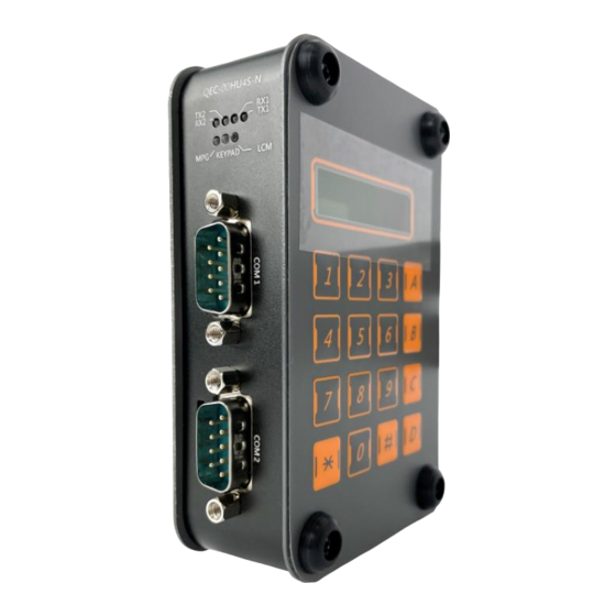
- Page 1 ICOP Technology Inc. User Manual QEC-RXXHU EtherCAT Slave HID Module With RS232/485, MPG, LCM and Keypad (Revision 3.0) QEC-RXXHU User Manual Ver.3 January, 2024...
- Page 2 ICOP Technology Inc. REVISION DATE VERSION DESCRIPTION 2022/09/01 Version 1.0 New Release. 2023/09/24 Version 2.0 Updated Product Specifications. 2024/1/11 Version 3.0 Add Getting Started QEC-RXXHU User Manual Ver.3 January, 2024...
- Page 3 No part of this manual may be reproduced, copied, translated or transmitted, in whole or in part, in any form or by any means without the prior written permission of ICOP Technology Inc. ©Copyright 2024 ICOP Technology Inc. Ver.3 January, 2024 TRADEMARKS ACKNOWLEDGMENT ICOP®...
- Page 4 WARNING! DO NOT ATTEMPT TO OPEN OR TO DISASSEMBLE THE CHASSIS (ENCASING) OF THIS PRODUCT. PLEASE CONTACT YOUR DEALER FOR SERVICING FROM QUALIFIED TECHNICIAN. QEC-RXXHU User Manual Ver.3 January, 2024...
-
Page 5: Table Of Contents
2.3.2 Removing the wire from the connector ................15 Ch. 3 Hardware Installation ....................16 3.1 DIN-Rail installation ....................17 3.2 Removing QEC-RXXHU Unit .................. 18 Ch. 4 Getting Started ......................19 4.1 Hardware Preparation and Connection ..............21 4.2 Software/Development Environment ..............22 4.3 Connect to your PC and set up the environment ........... - Page 6 Ch. 5 Slave Information ....................... 36 5.1 ESI (EtherCAT Slave Information) file ..............37 5.2 Object Dictionary ....................37 5.2.1 Standard Objects (0x1000-0x1FFF) ................. 38 5.2.2 Manufacturer Objects (0x5000-0x5FFF) ................42 5.2.3 Especial Objects (0x6000-0xFFFF) ................46 Warranty ..........................47 QEC-RXXHU User Manual Ver.3 January, 2024...
-
Page 7: 1 General Information
General Information 1.1 Introduction 1.2 Specifications 1.3 Dimension 1.4 Mounting Instruction 1.5 Ordering Information QEC-RXXHU User Manual Ver.3 January, 2024... -
Page 8: Introduction
QEC-RXXHU has dimensions of 107.45 x 77.39 x 34 mm and can be conveniently installed in a system using a Din-Rail. It operates in a temperature range of -20°C to +70°C and features two network interfaces for EtherCAT network redundancy, which enhances system reliability and stability. -
Page 9: Specifications
2400,4800,9600,14400,19200,38400,57600,115200 Data width (bit) 5/6/7/8 Hardware Flow Control CTS/RTS Handwheel MPG Control Axes Quadrature A/B Phase with axes selection Input Jog and federate override Keypad Matrix LCD Module 2 lines, 16 characters per line QEC-RXXHU User Manual Ver.3 January, 2024... -
Page 10: Dimension
ICOP Technology Inc. 1.3 Dimension (Unit: mm) QEC-RXXHU User Manual Ver.3 January, 2024... -
Page 11: Mounting Instruction
ICOP Technology Inc. 1.4 Mounting Instruction QEC-RXXHU series is an easy-install design to help you set-up your modules easily. Please refer to Ch.3.1 DIN-Rail installation. DIN-Rill QEC-RXXHU User Manual Ver.3 January, 2024... -
Page 12: Ordering Information
QEC-R00HU6S-N: EtherCAT Slave HID module (MPG + Keypad + RS232 x2) ⚫ QEC-R00HU7S-N: EtherCAT Slave HID module (MPG + Keypad + LCM + RS232 x2) ⚫ QEC-R00HU9S-N: EtherCAT Slave HID module (MPG + Keypad + LCM + RS232/485 x2) ⚫ QEC-RXXHU User Manual Ver.3 January, 2024... -
Page 13: 2 Hardware System
ICOP Technology Inc. Hardware System 2.1 General Technical Data 2.2 Connector Summary 2.3 Wiring to the Connector QEC-RXXHU User Manual Ver.3 January, 2024... -
Page 14: General Technical Data
ICOP Technology Inc. 2.1 General Technical Data QEC-RXXHU User Manual Ver.3 January, 2024... -
Page 15: Connector Summary
Pin # Signal Name LAN2_TX+ LAN2_TX- LAN2_RX+ LAN2_RX- VS- (GND) VP- (GND) PoE LAN with the Red Housing; Regular LAN with Black Housing. L4, L5, L7, L8 pins are option, for RJ45 Power IN/OUT. QEC-RXXHU User Manual Ver.3 January, 2024... -
Page 16: Power Connector
2.2.2 Power Connector Vs for system power; Vp for peripheral power and backup power. Pin # Signal Name Pin # Signal Name Vs- (GND) Vp- (GND) Power Input voltage +19 to +50VDC Power Input (Typ. +24VDC) QEC-RXXHU User Manual Ver.3 January, 2024... -
Page 17: Power And Connection Status Leds
The device is in state Safe-Operation The device is in state Operation No error Blinking Invalid Configuration Single Flash Local Error Process Data Watchdog Timeout Double Flash EtherCAT Watchdog Timeout The device is in state Error QEC-RXXHU User Manual Ver.3 January, 2024... -
Page 18: Io Status Leds
LCM signal 2.2.5 RS232/485 Connector & Switch RS232/485 Connector No. Pin Assignment No. Pin Assignment RS485- RS485+/RXD Note: RS232 and RS485 cannot be used simultaneously. Switch Notation States RS485 RS232 Enable RS232 RS485 Enable QEC-RXXHU User Manual Ver.3 January, 2024... -
Page 19: Lcm
ICOP Technology Inc. 2.2.6 LCM LCD Module: 2 lines, 16 characters per line. 2.2.7 DIN-Rail installation Please refer to Ch.3.1 DIN-Rail installation. QEC-RXXHU User Manual Ver.3 January, 2024... -
Page 20: Keypad
ICOP Technology Inc. 2.2.8 Keypad Matrix: 4x4. 2.2.9 MPG No. Pin Assignment No. Pin Assignment AXIS_B0 AXIS_B1 AXIS_B2 MULTIPLE_B0 MULTIPLE_B1 EMERGENCY QEC-RXXHU User Manual Ver.3 January, 2024... -
Page 21: Wiring To The Connector
2.3 Wiring to the Connector 2.3.1 Connecting the wire to the connector Insulated Terminals Dimensions (mm) Position Ø D1 Ø d1 Ø D2 CN 0.5-6 CN 0.5-8 CN 0.5-10 10.0 2.3.2 Removing the wire from the connector QEC-RXXHU User Manual Ver.3 January, 2024... -
Page 22: 3 Hardware Installation
ICOP Technology Inc. Hardware Installation 3.1 DIN-Rail installation 3.2 Removing QEC-RXXHU Unit QEC-RXXHU User Manual Ver.3 January, 2024... -
Page 23: Din-Rail Installation
When you mount the QEC-RXXHU, releasing the DIN track mounting hook on the QEC-RXXHU is unnecessary. After you mount the QEC-RXXHU, make sure it is locked to the DIN Track. Note: Always turn OFF the Unit power supply and I/O power supply before connecting and removing the QEC-RXXHU. -
Page 24: Removing Qec-Rxxhu Unit
ICOP Technology Inc. 3.2 Removing QEC-RXXHU Unit Use a flat-blade screwdriver to remove the DIN Track mounting hook on the unit. Pull down and out the flat-blade screwdriver with force against the DIN track until you hear the DIN Track remove the hook. -
Page 25: 4 Getting Started
ICOP Technology Inc. Getting Started 4.1 Hardware Preparation and Connection 4.2 Software/Development Environment 4.3 Connect to your PC and set up the environment 4.4 Configuration and Operation 4.5 Access Further Documentation QEC-RXXHU User Manual Ver.3 January, 2024... - Page 26 ICOP Technology Inc. This chapter explains how to access the QEC-RXXHU modules through the QEC-M-01 (EtherCAT Master) and its software, 86Duino Coding IDE. The parameter settings are easy to configure, shortening the system installation and evaluation time. Note. QEC’s PoE (Power over Ethernet) In QEC product installations, users can easily distinguish between PoE and non-PoE: if the RJ45 house is red, it is PoE type, and if the RJ45 house is black, it is non-PoE type.
-
Page 27: Hardware Preparation And Connection
PoE. After powering on, you’ll see the power LED light up and verify that the “PWR” LED indicators are ON (green). Using the EtherCAT Out port (top side) connected to the EtherCAT In port of QEC-R11HU9S via RJ45 cable (powered by PoE). QEC-RXXHU User Manual Ver.3 January, 2024... -
Page 28: Software/Development Environment
After downloading, please unzip the downloaded zip file, no additional software installation is required, just double-click 86duino.exe to start the IDE. *Note: If Windows displays a warning, click Details once and then click the Continue Run button once. 86Duino Coding IDE 500+ looks like below. QEC-RXXHU User Manual Ver.3 January, 2024... -
Page 29: Connect To Your Pc And Set Up The Environment
Select the correct board: In the IDE's menu, select “Tools” ->” Board”- > QEC-M-01 (or the QEC-M master model you use). Select Port: In the IDE's menu, select “Tools”- >” Port” and select the USB port to connect to the QEC-M master (in this case, COM3 (QEC)). QEC-RXXHU User Manual Ver.3 January, 2024... -
Page 30: Configuration And Operation
The connected devices will be displayed after the EtherCAT network has been scanned. Press the "View" button in the lower left corner to check the device's status (Voltage, Current, and Temperature; View2) and operating time (Hours; View3). QEC-RXXHU User Manual Ver.3 January, 2024... -
Page 31: Step 2: Set The Parameters
This example will use the default settings and not change any settings; please click "Back" in the upper left corner to return. For the Device Information, you can refer to 5.2.1 Standard Objects (0x1000-0x1FFF) 5.2.2 Manufacturer Objects (0x5000-0x5FFF). QEC-RXXHU User Manual Ver.3 January, 2024... -
Page 32: Step 3: Generation The Code
Additional note: After 86EVA generates code, the following code will be automatically generated in the main program (.ino), and any of them missing will cause 86EVA not to work. #include “myeva.h”: Include EVA Header file EVA.begin() in setup(); : Initialize the EVA function QEC-RXXHU User Manual Ver.3 January, 2024... -
Page 33: Step 4: Upload The Code
You can confirm this by the RUN LED on your QEC slave device, which should light up. Additionally, the LED on the EtherCAT LAN ports will start blinking, indicating active operation. QEC-R11HU9S (Node 0) QEC-RXXHU User Manual Ver.3 January, 2024... -
Page 34: Ethercatdevice_Qecrxxhu Class
To obtain the full EtherCAT Master API User Manual, we encourage you to reach out to our sales team or email us directly at info@icop.com.tw. Our team is dedicated to providing you with comprehensive support and detailed information to enhance your experience with our products. QEC-RXXHU User Manual Ver.3 January, 2024... - Page 35 1. UART Port The following example is reading the data from the Serial Monitor in 86Duino IDE and transferring it from COM1 to COM2. After COM2 receives the data, we print it on the Serial Monitor. QEC-RXXHU User Manual Ver.3 January, 2024...
- Page 36 After uploading, you can input a number or letter to the Serial Monitor in 86Duino IDE. All data will transfer from COM1 to COM2. After COM2 receives the data, we print it on the Serial Monitor, as in the image below. QEC-RXXHU User Manual Ver.3 January, 2024...
- Page 37 LCM according to it. Buzzer will buzz when the keypad is pressed; among them, '#' is a clear LCM display and sets the print position to the first row, and '*' is a clear LCM display and sets the print position to the second row. QEC-RXXHU User Manual Ver.3 January, 2024...
- Page 38 LCM according to it. Buzzer will buzz when the keypad is pressed; among them, '#' is a clear LCM display and sets the print position to the first row, and '*' is a clear LCM display and sets the print position to the second row. QEC-RXXHU User Manual Ver.3 January, 2024...
- Page 39 In the following example, we want to read the data and status of the MPG of QEC-R11HU9S, and print out EMG, Enable, Axis, Ratio, Raw, Logical data through the Serial Monitor of 86Duino IDE. QEC-RXXHU User Manual Ver.3 January, 2024...
- Page 40 After the upload is completed, you can read the data and status of the MPG of QEC-R11HU9S, and view EMG, Enable, Axis, Ratio, Raw, Logical and other data through the Serial Monitor of 86Duino IDE. QEC-RXXHU User Manual Ver.3 January, 2024...
-
Page 41: Access Further Documentation
EtherCAT technology. For more info and sample request, please write to info@icop.com.tw, call your nearest ICOP Branch, or contact our Worldwide Official Distributor. QEC-RXXHU User Manual Ver.3 January, 2024... -
Page 42: 5 Slave Information
ICOP Technology Inc. Slave Information 5.1 ESI (EtherCAT Slave Information) file 5.2 Object Dictionary QEC-RXXHU User Manual Ver.3 January, 2024... -
Page 43: Esi (Ethercat Slave Information) File
0x1000, 0x1001, 0x1008, 0x1009, 0x100a, 0x1010, 0x1011, 0x1018, 0x10F0, 0x10F1, 0x10F3, 0x1c00, 0x1c32, 0x1c33 Entries less or equal one 8Bit shall not overlap byte borders. Entries greater 8Bit shall always start at an exact word border. QEC-RXXHU User Manual Ver.3 January, 2024... -
Page 44: Standard Objects (0X1000-0X1Fff)
Table 4-1: Device Name Type Device Name Type Device Name QEC-R00HU1S QEC-R11HU1S QEC-R00HU2S QEC-R11HU2S QEC-R00HU3S QEC-R11HU3S QEC-R00HU4S QEC-R11HU4S HID without PoE QEC-R00HU5S HID with PoE QEC-R11HU5S QEC-R00HU6S QEC-R11HU6S QEC-R00HU7S QEC-R11HU7S QEC-R00HU8S QEC-R11HU8S QEC-R00HU9S QEC-R11HU9S QEC-RXXHU User Manual Ver.3 January, 2024... - Page 45 QEC-R11HU9S 0x0086d402 Index 10F1 Error Settings Index Name Data type Flags Default 10F1:0 Error Settings UINT8 > 2 < 10F1:01 Local Error Reaction UINT32 0x00000001 (1) 10F1:02 Sync Error Counter Limit UINT32 0x0004 (4) QEC-RXXHU User Manual Ver.3 January, 2024...
- Page 46 UINT8 0x02 (2) 1C00:03 SubIndex 003 UINT8 0x03 (3) 1C00:04 SubIndex 004 UINT8 0x04 (4) Index 1C12 SyncManager 2 assignment Index Name Data type Flags Default 1C12:0 SyncManager 2 assignment UINT8 > 0 < QEC-RXXHU User Manual Ver.3 January, 2024...
- Page 47 Get Cycle Time UINT16 0x0000 (0) 1C33:09 Delay Time UINT32 0x00000000 (0) 1C33:0A Sync0 Cycle Time UINT32 0x00000000 (0) 1C33:0B SM-Event Missed UINT16 1C33:0C Cycle Time Too Small UINT16 0x0057 (87) 1C33:20 Sync Error BOOL QEC-RXXHU User Manual Ver.3 January, 2024...
-
Page 48: Manufacturer Objects (0X5000-0X5Fff)
> 2 < Write_KeyPad UINT8 ClearKeyPadString (WO) STRING(16) GetKeyPadString (RO) Index 0x5011 LCM Index Object Code DataType Name Default Description Read_LCM 0x5011 VARIABLE > 3 < Write_LCM UINT8 (RO) UINT8 Column 0x10 (RO) STRING(32) Buffer (WO) QEC-RXXHU User Manual Ver.3 January, 2024... - Page 49 (RW) 0:disable, 1:Enable (RW) only can work on hardware flow UINT8 control is disabled. UINT8 (RO) UINT8 (RW) UINT8 (RO) STRING(256) Tx (WO) STRING(256) Rx (RO) UINT8 ClearFIFO (WO) UINT8 Mode (RO) 1=RS232 Mode ,0=RS485 Mode QEC-RXXHU User Manual Ver.3 January, 2024...
- Page 50 (RW) 0:disable, 1:Enable (RW) only can work on hardware flow UINT8 control is disabled. UINT8 (RO) UINT8 (RW) UINT8 (RO) STRING(256) Tx (WO) STRING(256) Rx (RO) UINT8 ClearFIFO (WO) UINT8 Mode (RO) 1=RS232 Mode ,0=RS485 Mode QEC-RXXHU User Manual Ver.3 January, 2024...
- Page 51 (RW) The frequency of the tone in hertz. UINT32 Frequency 0x01 Min 1Hz Max 100KHz. (RW) The duration of the tone in UINT32 Duration 0x01 milliseconds. 0: keep playing. UINT8 Start (RW) 0:stop play, 1:start Playing Or Playing. QEC-RXXHU User Manual Ver.3 January, 2024...
-
Page 52: Especial Objects (0X6000-0Xffff)
(RW) Index 0xFxxx Device Object (0xF000 – 0xFFFF) Index Object Code DataType Name Default Description 0xF000 RECORD Modular Device Profile > 2 < UINT16 Index distance 0x10 (RO) UINT16 Maximum number of modules (R0) QEC-RXXHU User Manual Ver.3 January, 2024... -
Page 53: Warranty
All Trademarks appearing in this manuscript are registered trademark of their respective owners. All Specifications are subject to change without notice. © ICOP Technology Inc. 2024 QEC-RXXHU User Manual Ver.3 January, 2024...
Need help?
Do you have a question about the QEC-RXXHU and is the answer not in the manual?
Questions and answers