
Related Manuals for ICOP Technology QEC-RXXMP3S-N


Summary of Contents for ICOP Technology QEC-RXXMP3S-N
- Page 1 ICOP Technology Inc. User Manual QEC-RXXMP3S EtherCAT Slave Stepper Motor Controller Up to 3-axis stepper Motor control (Revision 1.3) QEC-RXXMP3S User Manual Ver.1.3 August, 2024...
- Page 2 ICOP Technology Inc. REVISION DATE VERSION DESCRIPTION 2023/11/02 Version 1.0 New Release. 2024/1/17 Version 1.1 Update Product Data. 2024/3/30 Version 1.2 Update Homing Method. Add index objects 0x50C1~0x50C6 to specify the 2024/8/14 Version 1.3 workpiece coordinates' offset position in G-code.
- Page 3 No part of this manual may be reproduced, copied, translated or transmitted, in whole or in part, in any form or by any means without the prior written permission of ICOP Technology Inc. ©Copyright 2024 ICOP Technology Inc. Ver.1.3 August, 2024 TRADEMARKS ACKNOWLEDGMENT ICOP®...
- Page 4 ICOP Technology Inc. SAFETY INFORMATION Read these safety instructions carefully. ⚫ Please carry the unit with both hands and handle it with caution. ⚫ Power Input voltage +19 to +48VDC Power Input (Typ. +24VDC) ⚫ Make sure the voltage of the power source is appropriate before connecting the ⚫...
-
Page 5: Table Of Contents
ICOP Technology Inc. Content Content ..........................iv Ch. 1 General Information ...................... 1 1.1 Introduction ......................2 1.2 Specifications ....................... 3 1.2.1 General Information ......................3 1.2.2 Stepper Driver Information ....................4 1.3 Dimension ......................5 1.4 Mounting Instruction ....................6 1.5 Ordering Information.................... - Page 6 ICOP Technology Inc. 4.4.1 PDO Mapping ........................38 4.4.2 PDO Assign ........................40 4.4.3 PDO Operation Process....................41 4.5 CAN application protocol over EtherCAT ............. 44 4.6 Synchronization Modes ..................45 4.6.1 Free Run......................... 45 4.6.2 SM2 Event ........................45 4.6.3 Distributed Clock ......................
-
Page 7: 1 General Information
General Information 1.1 Introduction 1.2 Specifications 1.3 Dimension 1.4 Mounting Instruction 1.5 Ordering Information QEC-RXXMP3S User Manual Ver.1.3 August, 2024... -
Page 8: Introduction
ICOP Technology Inc. Introduction The QEC-RXXMP series is an EtherCAT stepper motor open-loop controller capable of high-speed synchronization at 125μs while simultaneously driving three axes of two-phase bipolar stepper motors. Equipped with A, B, and Z encoder interfaces. The QEC-RXXMP series has passed the verification of conformance testing tools and is suitable for various traditional industrial automation applications, such as management and precise motion control. -
Page 9: Specifications
ICOP Technology Inc. Specifications 1.2.1 General Information General Connector Push-in Terminal (Euroblock) EMG-: White, EMG+: Dark Red Connector Color A+: Black, A-: Green, B+: Red, B-: Blue Limit+: Blue, Limit-: Brown Protocol EtherCAT (RJ-45 x2) Ethernet Standard IEEE 802.3 Transmission Rate... -
Page 10: Stepper Driver Information
ICOP Technology Inc. 1.2.2 Stepper Driver Information Stepper Motor Interface EtherCAT Drive Profile CiA402, G-code Minimum Communication Cycle 125 µs Synchronization Mode DC, SM2, FreeRun Profile Position (PP) Homing (HM: Support Method 19, 20, 21, 22) Compatible Operation Mode Cyclic Synchronous Position (CSP) -
Page 11: Dimension
ICOP Technology Inc. 1.3 Dimension (Unit: mm) QEC-RXXMP3S User Manual Ver.1.3 August, 2024... -
Page 12: Mounting Instruction
ICOP Technology Inc. 1.4 Mounting Instruction QEC-RXXMP series is an easy-install design to help you set-up your modules easily. Please refer to Ch.3.1 DIN-Rail installation. DIN-Rill QEC-RXXMP3S User Manual Ver.1.3 August, 2024... -
Page 13: Ordering Information
ICOP Technology Inc. 1.5 Ordering Information RJ45 power source Functions Feature Type Coating Input Output Stepper Motor Functions Standard QEC-R 1. Type: Code 1~4 R: EtherCAT Slave 2. RJ45 Power source: Code 5~6 0: RJ45 In/Out w/o power 1: RJ45 In/Out – Power Device 3. -
Page 14: 2 Hardware System
ICOP Technology Inc. Hardware System 2.1 General Technical Data 2.2 Connector Summary 2.3 Wiring to the Connector QEC-RXXMP3S User Manual Ver.1.3 August, 2024... -
Page 15: General Technical Data
ICOP Technology Inc. 2.1 General Technical Data QEC-RXXMP3S User Manual Ver.1.3 August, 2024... -
Page 16: Connector Summary
ICOP Technology Inc. 2.2 Connector Summary Description Type Narrative Num # RJ45 Connector 8-pin EtherCAT Interface (Gold finger) 8-pin Power Connector Power Socket 6-pin Power and Connection Status LEDs Status LEDs Drive Status LEDs Status LEDs Drive Motor Connector Push-in Terminal (Euroblock) -
Page 17: Ethercat Interface
ICOP Technology Inc. 2.2.1 EtherCAT Interface RJ45 Connectors. EC IN Pin # Signal Name Pin # Signal Name LAN1_TX+ LAN1_TX- LAN1_RX+ LAN1_RX- VS- (GND) VP- (GND) PoE LAN with the Red Housing; Regular LAN with Black Housing. L4, L5, L7, L8 pins are option, for RJ45 Power IN/OUT. -
Page 18: Power Connector
ICOP Technology Inc. 2.2.2 Power Connector Euroblock Connectors. 4-pins Power Input/Output & 2-pins FGND. Vs for system power; Vp for peripheral power and backup power. Pin # Signal Name Pin # Signal Name Vs- (GND) Vp- (GND) Power Input voltage +19 to +50VDC Power Input (Typ. +24VDC) QEC-RXXMP3S User Manual Ver.1.3 August, 2024... -
Page 19: Power And Connection Status Leds
ICOP Technology Inc. 2.2.3 Power and Connection Status LEDs Power Status LED Power input is 24V (typical). The LED status provide high/low voltage warning. Notation States Condition Description Voltage <= 50V and >= 45V When Vs and Vp voltages are confirmed to be Green LED On Voltage <= 26V and >= 19V... - Page 20 ICOP Technology Inc. Power ERROR Code table (Red LED Flashing Display (2 seconds/cycle)): Long Light Short Flash Description After microchip completes the BootLoad test, it proceeds to the APP program stage. 1 short flash microchip communication with the EtherCAT chip failed.
- Page 21 ICOP Technology Inc. Connection Status LEDs EtherCAT: PWR, RUN, LINK, and ERROR Status LEDs Notation Color States Description No link Green Blinking Link and activity Link without activity No link Green Blinking Link and activity Link without activity The device is in state INIT...
-
Page 22: Drive Status Leds
ICOP Technology Inc. 2.2.4 Drive Status LEDs Alarm, Home, and Motor Status LEDs. Notation Color Description ALERT Green Alert signal M1 HOME Green X-Limit (X-Home) signal M1 MOTOR Green X-axis Motor action signal M2 HOME Green Y-Limit (Y-Home) signal M2 MOTOR... -
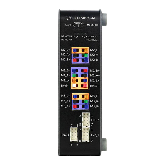
Page 23: Drive Motor Connector
ICOP Technology Inc. 2.2.5 Drive Motor Connector Euroblock Connectors. 3 x Stepper Motors (2-phase bipolar stepper motor) and 3 x home switch & Emergency Stop Input. Signal Name Signal Name M2_L+ M2_L- M2_A+ M2_A- M2_B+ M2_B- M1_B- M1_B+ M1_A- M1_A+... - Page 24 ICOP Technology Inc. Drive Motor Pins and Digital Input Description: Name Connector Color Signal Signal Description Default M2_A+ Black Input Motor 2 winding A+ M2_A- Green Input Motor 2 winding A- Y-Axis M2_B+ Input Motor 2 winding B+ M2_B- Blue...
-
Page 25: Encoder Connector
ICOP Technology Inc. 2.2.6 Encoder Connector TU2005 Connector Header. 3 x Encoder counter (A, B, Z), differential. Encoder Trace width: 15mil. Name Signal Signal Description Default ENC_1 Input Encoder 1 X-Axis ENC_2 Input Encoder 2 Y-Axis ENC_3 Input Encoder 3... - Page 26 ICOP Technology Inc. ENC_1: Description Pin # Pin # Description X_ENCV+ X_ENCV- ENCX-Z+ ENCX-Z- ENCX-B+ ENCX-B- ENCX-A+ ENCX-A- ENC_2 & ENC_3: Description Pin # Pin # Description ENCY-A- ENCY-A+ ENCY-B- ENCY-B+ ENCY-Z- ENCY-Z+ Y_ENCV- Y_ENCV+ ENCZ-A- ENCZ-A+ ENCZ-B- ENCZ-B+ ENCZ-Z-...
-
Page 27: Dip Switches For Adjustable Current
ICOP Technology Inc. 2.2.7 DIP Switches for Adjustable Current Piano switches (SW_1: CHP-080A; SW_2 and SW_3: CHP-081A). Switch Specifications: Operating Temperature -40 to +85°C Humidity −10 ~ 65 °C, Relative humidity 0 ~ 96 % Contact resistance 50 mΩ maximum Dimension 12.2 x 5.9 x 4.6 mm... - Page 28 ICOP Technology Inc. Applicable current for 3 types of motors. Users can see in the side case of QEC-RXXMP3S. 1234 STEP MODE 1000 Standby (motor off) 1001 1010 1/2 (A) (0%, 70%, 100%) 1011 7/2 (8) (0%, 100%) 1100 1101...
-
Page 29: Dip Switches Comparison Table
ICOP Technology Inc. 2.2.8 DIP Switches Comparison Table This table is for Ch.2.2.6 Encoder Connector Ch.2.2.7 DIP Switches for Adjustable Current. QEC-RXXMP3S User Manual Ver.1.3 August, 2024... -
Page 30: Din-Rail Installation
ICOP Technology Inc. 2.2.9 DIN-Rail installation Please refer to Ch.3.1 DIN-Rail installation. QEC-RXXMP3S User Manual Ver.1.3 August, 2024... -
Page 31: Wiring To The Connector
ICOP Technology Inc. 2.3 Wiring to the Connector 2.3.1 Connecting the wire to the connector Insulated Terminals Dimensions (mm) Position Ø D1 Ø d1 Ø D2 CN 0.5-6 CN 0.5-8 CN 0.5-10 10.0 2.3.2 Removing the wire from the connector QEC-RXXMP3S User Manual Ver.1.3 August, 2024... -
Page 32: Stepper Motor And Encoder Wiring
ICOP Technology Inc. 2.3.3 Stepper Motor and Encoder Wiring Four Lead Motor We use 86STEP-577609 in this example, which is a four-lead, two-phase 57 stepper motor with encoder. 86STEP can detect lost steps in cost-effective stepper motors. The optical encoder is embedded in the design to directly monitor the motor rotor position. - Page 33 ICOP Technology Inc. The figure below shows an example of three four-lead, two-phase motors (with encoder) connected to the QEC-RXXMP3S product. The encoder in the QEC-RXXMP3S can read various signals, including A, B, and Z. It's capable of interpreting pulse signals and determining motor rotation direction, CW (clockwise) or CCW (counter clockwise).
-
Page 34: Limit Switches
ICOP Technology Inc. 2.3.4 Limit Switches Limit Switches: 3 x home switch. Digital Input Digital Input channels Input type Sink Voltage level +19 to +50VDC Isolation Voltage Protection 2500 Vrms Application wiring: QEC-RXXMP3S User Manual Ver.1.3 August, 2024... -
Page 35: Emergency Stop
ICOP Technology Inc. 2.3.5 Emergency Stop Drive Motor power supply Description: Name Connector Color Signal Signal Description EMG- White Emergency stop (E-stop) is a safety mechanism used to shut off machinery in an emergency, when it need EMG+ Dark Red +8 to +42VDC to shut down simply and quickly via hardware switch. -
Page 36: 3 Hardware Installation
ICOP Technology Inc. Hardware Installation 3.1 DIN-Rail installation 3.2 Removing QEC-RXXMP Unit QEC-RXXMP3S User Manual Ver.1.3 August, 2024... -
Page 37: Din-Rail Installation
ICOP Technology Inc. 3.1 DIN-Rail installation Slide in the QEC-RXXMP on the hookup guides and press the QEC-RXXMP with a certain amount of force against the DIN track until the DIN Track mounting hook lock into place. When you mount the QEC-RXXMP, releasing the DIN track mounting hook on the QEC-RXXMP is unnecessary. -
Page 38: Removing Qec-Rxxmp Unit
ICOP Technology Inc. 3.2 Removing QEC-RXXMP Unit Use a flat-blade screwdriver to remove the DIN Track mounting hook on the unit. Pull down and out the flat-blade screwdriver with force against the DIN track until you hear the DIN Track remove the hook. -
Page 39: 4 Ethercat Communication
ICOP Technology Inc. EtherCAT Communication 4.1 EtherCAT Basics 4.2 EtherCAT Cabling 4.3 EtherCAT State Machine 4.4 Process Data Object 4.5 CAN application protocol over EtherCAT 4.6 Synchronization Modes QEC-RXXMP3S User Manual Ver.1.3 August, 2024... -
Page 40: Ethercat Basics
ICOP Technology Inc. 4.1 EtherCAT Basics EtherCAT (Ethernet for Control Automation Technology) is an Ethernet-based fieldbus system developed by Beckhoff Automation. The protocol is standardized in IEC 61158 and is suitable for both hard and soft real-time computing requirements in automation technology. -
Page 41: Ethercat State Machine
ICOP Technology Inc. 4.3 EtherCAT State Machine The state of the EtherCAT slave is controlled via the EtherCAT State Machine (ESM). Depending upon the state, different functions are accessible or executable in the EtherCAT slave. Specific commands must be sent by the EtherCAT master to the device in each state, particularly during the bootup of the slave. - Page 42 ICOP Technology Inc. Pre-Operational (Pre-Op) During the transition between Init and Pre-Op the EtherCAT slave checks whether the mailbox was initialized correctly. In Pre-Op state mailbox communication is possible, but not process data communication. The EtherCAT master initializes the sync manager channels for process data (from sync manager channel 2), the FMMU channels and, if the slave supports configurable mapping, PDO mapping or the sync manager PDO assignment.
-
Page 43: Process Data Object
ICOP Technology Inc. 4.4 Process Data Object Process Data Communication (PDO Communication) commands and receives Process Data Objects (PDO) with Master periodically. Data that will be delivered and received is already defined at the initial stage of communication by PDO Mapping. -
Page 44: Pdo Mapping
ICOP Technology Inc. 4.4.1 PDO Mapping TxPDO Mapping information to be delivered to the Master is to be set at 1A00, 1A10, and 1A20 Objects, and RxPDO Mapping information to receive a command from the Master is to be set at 1600, 1610, and 1620 Objects. - Page 45 ICOP Technology Inc. TxPDO Mapping Table: PDO Map Object Object Contents Index Object DataType Name 0x1A00 X Axis TxPdoMapping0 0x1A00 0x6041 0x00 UINT16 Statusword 0x1A00 0x6064 0x00 INT32 Position actual value 0x1A00 0x606C 0x00 INT32 Velocity Actual Value 0x1A00 0x60E4...
-
Page 46: Pdo Assign
ICOP Technology Inc. 4.4.2 PDO Assign PDO Assign is to set PDO Mapping Object will be assigned at SyncManager. PDO Mapping Object: SyncManager PDO Assign Object: Object Name Index Object 0x1600 Rx PDO Map0 0x1C12 SM2 assignment 0x1610 Rx PDO Map1... -
Page 47: Pdo Operation Process
ICOP Technology Inc. 4.4.3 PDO Operation Process For G-code Mode Operation Process: QEC-RXXMP3S User Manual Ver.1.3 August, 2024... - Page 48 ICOP Technology Inc. QEC-RXXMP3S User Manual Ver.1.3 August, 2024...
- Page 49 ICOP Technology Inc. QEC-RXXMP3S User Manual Ver.1.3 August, 2024...
-
Page 50: Can Application Protocol Over Ethercat
ICOP Technology Inc. 4.5 CAN application protocol over EtherCAT The CoE interface (CAN application protocol over EtherCAT) is used for parameter management of EtherCAT devices. EtherCAT slaves or the EtherCAT master manage fixed (read-only) or variable parameters required for operation, diagnostics, or commissioning. -
Page 51: Synchronization Modes
ICOP Technology Inc. 4.6 Synchronization Modes Synchronization modes provided by QEC-RXXMP3S are as follows. 4.6.1 Free Run In this mode, the EtherCAT slave device operates independently of the EtherCAT master's timing. The slave does not synchronize its operations with the master's clock or any other synchronization signals in the EtherCAT network. -
Page 52: Distributed Clock
ICOP Technology Inc. 4.6.3 Distributed Clock The Distributed Clock mode allows for precise synchronization of the EtherCAT slave device with the distributed clock system of the EtherCAT network. In this mode, the slave aligns its operations with either the SYNC0 or SYNC1 events, which are part of the distributed clock system. -
Page 53: 5 Getting Started
ICOP Technology Inc. Getting Started 5.1 Introduction 5.2 TwinCAT (PP Mode) 5.3 86Duino Coding IDE (PP Mode) 5.4 86Duino Coding IDE (G-code Mode) QEC-RXXMP3S User Manual Ver.1.3 August, 2024... -
Page 54: Notes: Qec's Poe (Power Over Ethernet)
ICOP Technology Inc. Notes: QEC’s PoE (Power over Ethernet) In QEC product installations, users can easily distinguish between PoE and non-PoE: if the RJ45 house is red, it is PoE type, and if the RJ45 house is black, it is non-PoE type. -
Page 55: Introduction
ICOP Technology Inc. 5.1 Introduction Welcome to the Quick Start Guide for the QEC-RXXMP3S EtherCAT Stepper Motor Driver. This section is designed to assist you in efficiently setting up and utilizing your new stepper motor driver. To facilitate this process, we will focus on two essential software tools: TwinCAT, which operates on a PC, and the 86Duino IDE, which is compatible with the QEC Master Series. -
Page 56: Twincat (Pp Mode)
ICOP Technology Inc. 5.2 TwinCAT (PP Mode) If you're ready to get your QEC-RXXMP3S EtherCAT Stepper Motor Driver up and running with TwinCAT, this section is for you. We're focusing on using the CiA402 Drive Profile in Profile Position (PP) Mode, perfect for when you need your motor to hit precise positions accurately. -
Page 57: Add The Qec-R11Mp3S To The Project
ICOP Technology Inc. 5.2.2 Add the QEC-R11MP3S to the Project This section assumes that the TwinCAT software is in Config Mode. 1. Scan for the QEC-RXXMP3S device. Right-click on the EtherCAT adapter that the QEC-RXXMP3S is attached to. In the drop-down menu that opens, select the “Scan Device”... - Page 58 ICOP Technology Inc. 3. Confirm “Yes” to start the scan. 4. Choose “No” when TwinCAT asks you to activate Free Run. We need to set up the PP mapping to the PDO before operation. 5. The QEC-R11MP3S will appear in the device tree and the name will typically begin with “Box”.
-
Page 59: Start To Configure The Qec-R11Mp3S
ICOP Technology Inc. 5.2.3 Start to Configure the QEC-R11MP3S 1. Click on the “Process Data” tab, and click "2 33 Outputs" in the "Sync Manager:" field to set Outputs PDO Mapping. The original check boxes in the "PDO Assignment (0x1C12):" field are 0x1600, 0x1610, and 0x1620. - Page 60 ICOP Technology Inc. 3. Click "3 60 Inputs" in the "Sync Manager:" column to set Inputs PDO Mapping. The original check in the "PDO Assignment (0x1C13):" column is 0x1A00, 0x1A10, 0x1A20, and the default check setting is used in CSP or CSV mode.
- Page 61 ICOP Technology Inc. 5. After setting, click "Reload I/O Devices (F4)," marked in red in the picture below, to update the PDO Mapping settings. After clicking, a window will pop up asking whether to "Activate Free Run." Please click "Yes."...
-
Page 62: Control The Qec-R11Mp3S
ICOP Technology Inc. 5.2.4 Control the QEC-R11MP3S Next, please change the Controlword in order to let the CiA-402 state machine enter the Operation Enable state. 1. Select the drop-down list of QEC-R11MP3S in the left window. And choose “Controlword” in the drop-down list of the "X Asix RxPdoMapping4". - Page 63 ICOP Technology Inc. 3. Again, enter 15 in the pop-up window to change the value of Controlword to 15. 4. Next, select the BOX 1(QEC-R11MP3S) in the left window. Click the "CoE - Online" page to view all objects and perform Mailbox transmission. Find object 0x6060 and double-click the object with the left mouse button.
- Page 64 ICOP Technology Inc. 5. Enter 1 in the pop-up window to set the value of object 0x6060 to 1, and specify the operation mode to Profile Position (PP) mode. 6. Expand "X Axis RxPdoMapping4" and click "Target position", click "Write..." on the "Online"...
- Page 65 ICOP Technology Inc. 7. Set Profile velocity to 6400. 8. Set Profile acceleration to 6400. QEC-RXXMP3S User Manual Ver.1.3 August, 2024...
- Page 66 ICOP Technology Inc. 9. Set Controlword to 0x001F to make the New set-point bit 1. Then, your QEC-R11MP3S starts to drive the motor to rotate for 32,000 steps with a velocity of 6,400 and an acceleration of 6,400. 10. When the New set-point bit changes from 0 to 1, MP3S will receive the new Target position, Profile velocity, and Profile acceleration commands.
-
Page 67: 86Duino Coding Ide (Pp Mode)
ICOP Technology Inc. 5.3 86Duino Coding IDE (PP Mode) This section covers the basics of using the 86Duino IDE to program and control the QEC-R11MP3S. The 86Duino Coding IDE, with its user-friendly interface and compatibility with the Arduino programming environment, offers a straightforward way to write, upload, and manage code for the QEC Master Series devices to achieve quick and easy control of the EtherCAT Network devices and Slaves, including the QEC-R11MP3S. -
Page 68: Download Software
ICOP Technology Inc. 5.3.2 Download Software Download 86duino IDE from https://www.qec.tw/software/. After downloading, please unzip the downloaded zip file, no additional software installation is required, just double-click 86duino.exe to start the IDE. *Note: If Windows displays a warning, click Details once and then click the Continue Run button once. -
Page 69: Connect To Your Pc And Set Up The Environment
ICOP Technology Inc. 5.3.3 Connect to your PC and set up the environment Follow the steps below to set up the environment: 1. Connect the QEC-M-01P to your PC via a Micro USB to USB cable (86Duino IDE installed). 2. Turn on the QEC power. -
Page 70: Development Method 1: Write Code
ICOP Technology Inc. 5.3.4 Development Method 1: Write code In this example, we will control a single-axis stepper motor using the QEC-R11MP3S controller via the EtherCAT communication protocol. We will use the Profile Position (PP) mode from the CiA402 standard, which is a position control mode with a predefined trajectory. Through the profilePositionBegin() function, we will set the motor to move to a specified position of 81920, starting the motion with a speed and acceleration of 10000. - Page 71 ICOP Technology Inc. pp_state++; break; case 1: motor.profilePositionEnd(); pp_state++; break; case 2: if (motor.driveIsTargetReached()) pp_state++; break; case 3: if (motor.profilePositionBegin(1000, 10000, 5000) == 0) pp_state++; break; case 4: motor.profilePositionEnd(); pp_state++; break; case 5: if (motor.driveIsTargetReached()) { pp_state = 0; break;...
- Page 72 ICOP Technology Inc. Or you can use EtherCAT CiA402 objects, you can use the dedicated EtherCAT CiA402 library. #include "Ethercat.h" EthercatMaster EcatMaster; EthercatDevice_CiA402 motor; int pp_state = 0; void setup() { EcatMaster.begin(); motor.attach(0, 0, EcatMaster); motor.driveSetMode(CIA402_PP_MODE); EcatMaster.start(1000000, ECAT_SYNC); motor.driveEnable(); void loop() {...
- Page 73 ICOP Technology Inc. if (motor.driveIsTargetReached()) { pp_state = 0; break; After the upload is complete, you can see the motor move to the specified position and then return to the initial position. This process will repeat continuously. Note: Once the code is written, click on the toolbar to...
-
Page 74: Development Method 2: Use 86Eva With Code
ICOP Technology Inc. 5.3.5 Development Method 2: Use 86EVA with code 86EVA is a graphical EtherCAT configurator based on the EtherCAT Library in the 86Duino IDE and is one of the development kits for 86Duino. The user can use it to configure the EtherCAT network quickly and start programming. -
Page 75: Step 2: Set The Parameters
ICOP Technology Inc. The connected devices will be displayed after the EtherCAT network has been scanned. Press the "View" button in the lower left corner to check the device's status (Voltage, Current, and Temperature; View2) and operating time (Hours; View3). - Page 76 ICOP Technology Inc. QEC-R11MP3S-N Press twice on the image of the QEC-R11MP3S to see the parameter settings. Please note the "Device Mode" field in "General," which has two options: CiA-402 Servos and G-code Machine. This example uses the CiA-402 Servos mode.
- Page 77 ICOP Technology Inc. Step 3: Generate the code Once you've set your device's parameters, go back to the home screen and press the "Code Generation" button in the bottom right corner. When you're done, double-click the OK button to turn off 86EVA, or it will close in 10 seconds.
- Page 78 ICOP Technology Inc. The generated code and files are as follows: sketch_dec28b: Main Project (.ino, depending on your project name) ChatGPT.h: Parameters to provide to ChatGPT referred myeva.cpp: C++ program code of 86EVA myeva.h: Header file of 86EVA ...
- Page 79 ICOP Technology Inc. Step 4: Write the code In this example, we will control a single-axis stepper motor using the QEC-R11MP3S controller via the EtherCAT communication protocol. We will use the Profile Position (PP) mode from the CiA402 standard, which is a position control mode with a predefined trajectory. Through the profilePositionBegin() function, we will set the motor to move to a specified position of 81920, starting the motion with a speed and acceleration of 10000.
- Page 80 ICOP Technology Inc. pp_state++; break; case 4: motor.profilePositionEnd(); pp_state++; break; case 5: if (VirtualServo1.cia402GetServo()->driveIsTargetReached()) { pp_state = 0; break; After the upload is complete, you can see the motor move to the specified position and then return to the initial position. This process will repeat continuously.
-
Page 81: 86Duino Coding Ide (G-Code Mode)
ICOP Technology Inc. 5.4 86Duino Coding IDE (G-code Mode) In this section, we will show you how to use the EtherCAT Master QEC-M-01P and the QEC-RXXMP3S Series (EtherCAT Slave, 3-axis Stepper Motor Controller). We will be operating G-code mode. We use the same software and hardware with 5.3 86Duino Coding IDE (PP... - Page 82 ICOP Technology Inc. void setup() { EcatMaster.begin(); Slave1.attach(0, EcatMaster); EcatMaster.attachCyclicCallback(myCallback); EcatMaster.start(1000000, ECAT_SYNC); Slave1.machineServoOn(); void loop() { Slave1.machineGcode("G1 X100 F1000"); delay(6000); Slave1.machineGcode("G1 X0 F10000"); delay(1000); After the upload is complete, you can see the X-axis motor move to position 100 at a speed of 1000, after which the program pauses for 6 seconds to ensure the action is completed.
-
Page 83: Development Method 2: Use 86Eva With Code
ICOP Technology Inc. 5.4.2 Development Method 2: Use 86EVA with code 86EVA is a graphical EtherCAT configurator based on the EtherCAT Library in the 86Duino IDE and is one of the development kits for 86Duino. The user can use it to configure the EtherCAT network quickly and start programming. - Page 84 ICOP Technology Inc. The connected devices will be displayed after the EtherCAT network has been scanned. Press the "View" button in the lower left corner to check the device's status (Voltage, Current, and Temperature; View2) and operating time (Hours; View3).
- Page 85 ICOP Technology Inc. QEC-R11MP3S-N Press twice on the image of the QEC-R11MP3S to see the parameter settings. Please note the "Device Mode" field in "General," which has two options: CiA-402 Servos and G-code Machine. This example uses the G-code Machine mode.
- Page 86 ICOP Technology Inc. After finishing, click "Back" in the upper left corner to return. This action sets the three-axis drive control of the QEC-R11MP3S to be the VirtualCNC Controller1 of the EVA. Step 3: Generate the code Once you've set your device's parameters, go back to the home screen and press the "Code Generation"...
- Page 87 ICOP Technology Inc. The generated code and files are as follows: sketch_dec28b: Main Project (.ino, depending on your project name) ChatGPT.h: Parameters to provide to ChatGPT referred myeva.cpp: C++ program code of 86EVA myeva.h: Header file of 86EVA ...
- Page 88 ICOP Technology Inc. Step 4: Write the code Here's an example of reference code: #include "myeva.h" void setup() { EVA.begin(); VirtualCNC1.begin(); void loop() { VirtualCNC1.gcode("G1 X100 F1000"); delay(6000); VirtualCNC1.gcode("G1 X0 F10000"); delay(1000); After the upload is complete, you can see the X-axis motor move to position 100 at a speed of 1000, after which the program pauses for 6 seconds to ensure the action is completed.
-
Page 89: 6 Slave Information
ICOP Technology Inc. Slave Information 6.1 ESI (EtherCAT Slave Information) file 6.2 Object Dictionary QEC-RXXMP3S User Manual Ver.1.3 August, 2024... -
Page 90: Esi (Ethercat Slave Information) File
ICOP Technology Inc. 6.1 ESI (EtherCAT Slave Information) file The ESI files contain information unique to the EtherCAT Slave Terminals in XML format. You can load an ESI file into the Support Software to easily allocate Slave Terminal process data and other settings. -
Page 91: Standard Objects
ICOP Technology Inc. 6.2.1 Standard Objects Index 1000 Device type Index Name Data type Flags Default 1000 Device type UINT32 0x00040192 (262546) Index 1001 Error register Index Name Data type Flags Default 1001 Error register UINT8 0x00 (0) Index 1008 Device name... - Page 92 ICOP Technology Inc. Index 100A Software version Index Name Data type Flags Default Depends on the version of the 100A Software version STRING product you have. Index 1018 Identity Index Name Data type Flags Default 1018:0 Identity UINT8 > 4 <...
-
Page 93: Rxpdo Mapping Objects
ICOP Technology Inc. 6.2.2 RxPDO Mapping Objects RxPDO Mapping (0x1600 - 0x17FF). If no RxPDO mapping object is defined the will be created automatically. Index 1600 X Axis RX PDO Mapping0 Index Name Data type Flags Default Description 1600:0 X Axis RxPdoMapping0 UINT8 >... - Page 94 ICOP Technology Inc. Index 1604 X Axis RX PDO Mapping4 Index Name Data type Flags Default Description 1604:0 X Axis RxPdoMapping4 UINT8 > 4 < RX PDO Mapping for PP. 1604:01 SubIndex 001 UINT32 0x6040:00, 16 Map control word. 1604:02...
- Page 95 ICOP Technology Inc. Index 1610 Y Axis RX PDO Mapping0 Index Name Data type Flags Default Description 1610:0 Y Axis RxPdoMapping0 UINT8 > 4 < RX PDO Mapping for CSP, CSV. 1610:01 SubIndex 001 UINT32 0x6840:00, 16 Map control word.
- Page 96 ICOP Technology Inc. Index 1620 Z Axis RX PDO Mapping0 Index Name Data type Flags Default Description 1620:0 Z Axis RxPdoMapping0 UINT8 > 4 < RX PDO Mapping for CSP, CSV. 1620:01 SubIndex 001 UINT32 0x7040:00, 16 Map control word.
- Page 97 ICOP Technology Inc. Index 1630 G code RX PDO Mapping0 Index Name Data type Flags Default Description 1630:0 G code RxPdoMapping0 UINT8 > 6 < RX PDO Mapping for Gcode mode. 1630:01 SubIndex 001 UINT32 0x50D0:00, 16 Map G code header.
-
Page 98: Txpdo Mapping Objects
ICOP Technology Inc. 6.2.3 TxPDO Mapping Objects TxPDO Mapping (0x1A00 - 0x1BFF). If no TxPDO mapping object is defined the will be created automatically. Index 1A00 X Axis TX PDO Mapping0 Index Name Data type Flags Default Description 1A00:0 X Axis TxPdoMapping0 UINT8 >... - Page 99 ICOP Technology Inc. Index 1A02 X Axis TX PDO Mapping2 Index Name Data type Flags Default Description 1A02:0 X Axis TxPdoMapping2 UINT8 > 6 < TX PDO Mapping for CSV. 1A02:01 SubIndex 001 UINT32 0x6041:00, 16 Map control word. 1A02:02...
- Page 100 ICOP Technology Inc. Index 1A04 X Axis TX PDO Mapping4 Index Name Data type Flags Default Description 1A04:0 X Axis TxPdoMapping4 UINT8 > 5 < TX PDO Mapping for PP. 1A04:01 SubIndex 001 UINT32 0x6041:00, 16 Map status word. 1A04:02...
- Page 101 ICOP Technology Inc. Index 1A12 Y Axis TX PDO Mapping2 Index Name Data type Flags Default Description 1A12:0 Y Axis TxPdoMapping2 UINT8 > 6 < TX PDO Mapping for CSV. 1A12:01 SubIndex 001 UINT32 0x6841:00, 16 Map control word. 1A12:02...
- Page 102 ICOP Technology Inc. Index 1A21 Z Axis TX PDO Mapping1 Index Name Data type Flags Default Description 1A21:0 Z Axis TxPdoMapping1 UINT8 > 5 < TX PDO Mapping for CSP. 1A21:01 SubIndex 001 UINT32 0x7041:00, 16 Map status word. 1A21:02...
- Page 103 ICOP Technology Inc. Index 1A30 G code TX PDO Mapping0 Index Name Data type Flags Default Description 1A30:0 G code TxPdoMapping0 UINT8 > 14 < TX PDO Mapping for G-code mode. 1A30:01 SubIndex 001 UINT32 0x50E0:00, 16 Map G-code statusword.
-
Page 104: Sync Manager Objects
ICOP Technology Inc. 6.2.4 Sync Manager Objects Index 1C00 Sync manager type Index Name Data type Flags Default 1C00:0 Sync manager type UINT8 > 4 < 1C00:01 SubIndex 001 UINT8 0x01 (1) 1C00:02 SubIndex 002 UINT8 0x02 (2) 1C00:03 SubIndex 003... - Page 105 ICOP Technology Inc. Index 1C32 SM Output Parameters Index Name Data type Flags Default 1C32:0 SM output parameter UINT8 > 3 < 1C32:01 Synchronization Type UINT16 0x0000 (0) 1C32:02 Cycle Time UINT32 0x00000000 (0) 1C32:03 SubIndex 003 Synchronization Types 1C32:04...
- Page 106 ICOP Technology Inc. Index 1C33 SM input parameter Index Name Data type Flags Default 1C33:0 SM input parameter UINT8 > 32 < 1C33:01 Synchronization Type UINT16 0x0000 (0) 1C33:02 Cycle Time UINT32 0x00000000 (0) 1C33:03 SubIndex 003 1C33:04 Synchronization Types...
-
Page 107: Manufacturer Objects
ICOP Technology Inc. 6.2.5 Manufacturer Objects Index 0x5xxn Manufacturer Objects Index Name Data type Flags Default Description 5000 SP_Voltage UINT16 Read SP Voltage 5001 SP_Current UINT16 Read SP Current 5002 PP_Voltage UINT16 Read PP Voltage 5003 PP_Current UINT16 Read PP Current... -
Page 108: Motor Objects
ICOP Technology Inc. 6.2.6 Motor Objects Index 0x5010 Pulse Period Index Name Data type Flags Default 5010 PulsePeriod UINT32 0x00000010 (16) Index 0x5011 Motor Pulse Position distance of motor full rotation. If set 16 micro-steps per full step and use stepper motor features a 1.8°... - Page 109 ICOP Technology Inc. Index 0x5012 Initialize EEPROM MP3S can restore object setting to EEPROM. Write corresponding value to object 0x5012 will initialize EEPROM: 0x1108: initialize common objects 0x1104: initialize objects of CiA-402 0x1100: initialize objects of G-code mode ...
- Page 110 ICOP Technology Inc. Index 0x5020 ENC Mode Additional position encoder value (0x60E4/0x68E4 /0x70E4) is updated via encoder interface (ENC_1/ ENC_2/ENC_3). Input signal mode of encoder interface can be set by ENC Mode 0x5020. Index Name Data type Flags Default 5020:0...
- Page 111 ICOP Technology Inc. MODE_STEP_DIR MODE_CWCCW QEC-RXXMP3S User Manual Ver.1.3 August, 2024...
- Page 112 ICOP Technology Inc. MODE_AB_PHASE MODE_STEP_DIR_x2 QEC-RXXMP3S User Manual Ver.1.3 August, 2024...
- Page 113 ICOP Technology Inc. MODE_CWCCW_x2 MODE_AB_PHASE_x2 QEC-RXXMP3S User Manual Ver.1.3 August, 2024...
- Page 114 ICOP Technology Inc. Index 0x5021 ENC Digital Filter Unit of ENC Digital Filter is 10 nanoseconds. If set ENC Digital Filter to 100, encoder interface will delay sampling for 1000 ns after rising/falling edge trigger. Index Name Data type Flags...
- Page 115 ICOP Technology Inc. Index 0x5023 ENC Range Set an upper bound value of encoder counter. When the counter value increase up to the upper bound, then back to zero. Otherwise, When the counter value decrease to the lower bound, then back to max value.
- Page 116 ICOP Technology Inc. Index 0x5025 ENC Write Writing object 0x5025 would set encoder value to writing value. Additional position encoder value (0x60E4/0x68E4/ 0x70E4) would be updated to the same value. Index Name Data type Flags Default 5025:0 ENC Write UINT8 >...
- Page 117 ICOP Technology Inc. Index 0x5030 Home Direction Set homing direction. Index Name Data type Flags Default 5030 Home Direction UINT8 Bit 0, 1, and 2 set the direction of finding the Home Limit. Reserved Z direction Y direction X direction...
- Page 118 ICOP Technology Inc. Index 0x50C1 G54 Work Offset Read/Write work offset of G54. 0x50C1.1: G54 X-axis coordinate. 0x50C1.2: G54 Y-axis coordinate. 0x50C1.3: G54 Z-axis coordinate. Index Name Data type Flags Default 50C1:0 G54_WorkOffset 50C1:01 REAL64 50C1:02 REAL64...
- Page 119 ICOP Technology Inc. Index 0x50C3 G56 Work Offset Read/Write work offset of G56. 0x50C3.1: G56 X-axis coordinate. 0x50C3.2: G56 Y-axis coordinate. 0x50C3.3: G56 Z-axis coordinate. Index Name Data type Flags Default 50C3:0 G56_WorkOffset 50C3:01 REAL64 50C3:02 REAL64...
- Page 120 ICOP Technology Inc. Index 0x50C5 G58 Work Offset Read/Write work offset of G58. 0x50C5.1: G58 X-axis coordinate. 0x50C5.2: G58 Y-axis coordinate. 0x50C5.3: G58 Z-axis coordinate. Index Name Data type Flags Default 50C5:0 G58_WorkOffset 50C5:01 REAL64 50C5:02 REAL64...
- Page 121 ICOP Technology Inc. Index 0x50D0 G Code Header Transmit G-code via PDO: 0x50D0 and 0x50D1 are designed to transmit G-code via PDO. Index Name Data type Flags Default 50D0 G Code Header UINT16 0x0000 (0) The header of the G code string data during PDO transmission. The functions of each bit in the header are as follows: [15 –...
- Page 122 ICOP Technology Inc. Index 0x50D1 G Code string Transmit G-code via PDO: 0x50D0 and 0x50D1 are designed to transmit G-code via PDO. Object for PDO transmission, the object type is string (26 bytes). Index Name Data type Flags Default 50D1 G Code string ARRAY [0..25] OF BYTE...
- Page 123 ICOP Technology Inc. Index 0x50D3 Max Velocity Set maximum value of feed-rate. Velocity unit is mm per second. 0x50D3.1: X axis, object type is REAL64 0x50D3.2: Y axis 0x50D3.3: Z axis Index Name Data type Flags Default...
- Page 124 ICOP Technology Inc. Index 0x50D6 Homing Speed Set homing speed of XYZ axes. Unit of speed is mm per minute. Index Name Data type Flags Default 50D6:0 Homing Speed UINT8 > 0 < 50D6:01 X axis REAL64 50D6:02 Y axis...
- Page 125 ICOP Technology Inc. Index 0x50D8 Home Set 0x50D8 will execute Homing. Motor will rotate in the negative direction until home switch is triggered. Definition of 0x50D8: 0 → 2: Start homing 2 → 0: Stop homing Index Name...
- Page 126 ICOP Technology Inc. Index 0x50DA Clear EMG Stop When object 0x50D9 equals 0, set 0x50DA will execute Clear EMG Stop. Definition of 0x50DA: 0: Nothing 1: Execute Clear EMG Stop Index Name Data type Flags Default 50DA Clear EMG Stop...
- Page 127 ICOP Technology Inc. Index 0x50DC Default Homing SPD Object 0x50DC provide a default value of Homing Speed(0x50D6). The value of 0x50D6 will be set to the value of 0x50DC after G-code machine boots. Unit of 0x50DC is mm per minute.
- Page 128 ICOP Technology Inc. Index 0x50E0 G code Statusword Index Name Data type Flags Default 50E0 G code Statusword UINT16 0x0000 (0) [15-8] [3 – 0] Error Code Discard Odd Even String Segment Counter Error Code: After changing the Finish bit of G Code Header to 1, the Error Code of G Code ...
- Page 129 ICOP Technology Inc. Discard Bit of 0x50E0 If Odd Even bit of 0x50D0 changed before finish bit of 0x50D0 is set to 1, discard bit of 0x50E0 would be set to 1. PDO Cycle 0x50D0 0x50D1 0x50E0 0x0000 0x0000 0x0001 "G2 X2000000.0 Y2000000.0 "...
- Page 130 ICOP Technology Inc. Index 0x50E1 Machine Status Index Name Data type Flags Default 50E1 Machine Status UINT8 0x00 (0) [7 – 4] Reserved Emergency Stop Is Moving Homing attained Servo On/Off If this bit is 1, it means that the EmgStop of the...
- Page 131 ICOP Technology Inc. Index 0x50E2 Actual Position Read-only file, returns the position of the three axes of XYZ in mm. Index Name Data type Flags Default 50E2:0 Actual Position UINT8 > 0 < 50E2:01 X axis REAL64 50E2:02 Y axis...
- Page 132 ICOP Technology Inc. Index 0x50FB Motor Mapping By default, X-axis corresponds to the M1 motor interface, Y-axis corresponds to M2, Z-axis corresponds to M3. Writing object 0x50FB and then rebooting device will swap the motor mappings. Index Name Data type...
- Page 133 ICOP Technology Inc. Index 0x50FD Reverse Direction If the value of object 0x50FD is 0, the motor direction is the default direction. If 1, the motor direction is reversed. This object can only be set when Servo-Off. Index Name Data type...
-
Page 134: Especial Objects (0X6000-0Xffff)
ICOP Technology Inc. 6.2.7 Especial Objects (0x6000-0xFFFF) For especial objects description. Index 0x6nnx Input Data of the Module (0x6000 - 0x6FFF) For Index 0x6000 - 0x6FFF, the input data of the EtherCAT Slave module. Index 0x603F Error Code Index Name... - Page 135 ICOP Technology Inc. Index 0x6060 Modes of operation Mode Write. Index Name Data type Flags Default 6060 Modes of operation INT8 Index 0x6061 Modes of operation display Index Name Data type Flags Default 6061 Modes of operation display INT8 0x00...
- Page 136 ICOP Technology Inc. Index 0x607D Software position limit Set Position Limit. Recommended if CSP is supported. Index Name Data type Flags Default 607D:0 Software position limit 607D:01 Min position limit INT32 RO, wr_preop 0x88CA6C00 607D:02 Max position limit INT32 RO, wr_preop...
- Page 137 ICOP Technology Inc. Index 0x6085 Quick stop deceleration Can’t be zero. Index Name Data type Flags Default 6085 Quick stop deceleration UINT32 0x00000001 (1) Index 0x608B Velocity notation index Index Name Data type Flags Default 608B Velocity notation index INT8 Index 0x608C Velocity dimension index Save to EEPROM.
- Page 138 ICOP Technology Inc. Index 0x6098 Homing method Specify the return-to-origin method. Possible values are: 19, 20, 21, 22. Set other values and perform a return to origin. If this occurs, a homing error occurs, and 1 is returned to Bit13: Homing error of statusword.
- Page 139 ICOP Technology Inc. Index 0x6099 Homing speed Can’t be zero. Index Name Data type Flags Default 6099:0 Homing speed UINT8 > 2 < 6099:01 Speed for searching switch UINT32 0x00000001 (1) 6099:02 Speed for searching zero UINT32 0x00000001 (1) Index 0x609A Homing acceleration Can’t be zero.
- Page 140 ICOP Technology Inc. Index 0x60BA Touch probe position 1 positive value Index Name Data type Flags Default 60BA Touch probe position 1 positive value INT32 Index 0x60BB Touch probe position 1 negative value Index Name Data type Flags Default 60BB...
- Page 141 ICOP Technology Inc. Index 0x60EF Motor resolution Index Name Data type Flags Default 60EF Motor resolution UINT32 0x00000C80 (3200) Index 0x60FD Digital inputs Index Name Data type Flags Default 60FD Digital inputs UINT32 0x00000000 (0) Index 0x60FF Target velocity Mandatory if PV or CSV is supported.
- Page 142 ICOP Technology Inc. Index 0x6840 Control word Index Name Data type Flags Default 6840 Controlword UINT16 0x0000 (0) Index 0x6841 Status word Index Name Data type Flags Default 6841 Statusword UINT16 0x0000 (0) Index 0x6860 Modes of operation Mode write.
- Page 143 ICOP Technology Inc. Index 0x687C Home offset Index Name Data type Flags Default 687C Home offset INT32 Index 0x687D Software position limit Set Position Limit. Recommended if CSP is supported. Index Name Data type Flags Default 687D:0 Software position limit...
- Page 144 ICOP Technology Inc. Index 0x6883 Profile acceleration Can’t be zero. Index Name Data type Flags Default 6883 Profile acceleration UINT32 0x00000001 (1) Index 0x688B Velocity notation index Index Name Data type Flags Default 688B Velocity notation index INT8 Index 0x688C Velocity dimension index Save to EEPROM.
- Page 145 ICOP Technology Inc. Index 0x68B0 Position offset Index Name Data type Flags Default 68B0 Position offset INT32 Index 0x68B1 Velocity offset Index Name Data type Flags Default 68B1 Velocity offset INT32 Index 0x68B8 Touch probe function Index Name Data type...
- Page 146 ICOP Technology Inc. Index 0x68D5 Touch probe 1 positive edge counter Index Name Data type Flags Default 68D5 Touch probe 1 positive edge counter UINT16 0x0000 (0) Index 0x68D6 Touch probe 1 negative edge counter Index Name Data type Flags...
- Page 147 ICOP Technology Inc. Index 0x7nnx Output Data of the Module (0x7000 - 0x7FFF) For Index 0x7000 - 0x7FFF, the output data of the EtherCAT Slave module. Index 0x7040 Control word Index Name Data type Flags Default 7040 Controlword UINT16 0x0000 (0)
- Page 148 ICOP Technology Inc. Index 0x707A Target position Mandatory if CSP is supported. Index Name Data type Flags Default 707A Target position INT32 Index 0x707C Home offset Set Home Position. Index Name Data type Flags Default 707C Home offset INT32 Index 0x707D Software position limit Set Position Limit.
- Page 149 ICOP Technology Inc. Index 0x7081 Profile velocity Can’t be zero. Index Name Data type Flags Default 7081 Profile velocity UINT32 0x00000001 (1) Index 0x7083 Profile acceleration Can’t be zero. Index Name Data type Flags Default 7083 Profile acceleration UINT32 0x00000001 (1)
- Page 150 ICOP Technology Inc. Index 0x709A Homing acceleration Can’t be zero. Index Name Data type Flags Default 709A Homing acceleration UINT32 0x00000001 (1) Index 0x70B0 Position offset Index Name Data type Flags Default 70B0 Position offset INT32 Index 0x70B1 Velocity offset...
- Page 151 ICOP Technology Inc. Index 0x70C2 Interpolation time period Index Name Data type Flags Default 70C2:0 Interpolation time period 70C2:01 Interpolation time period value UINT8 0x00 (0) 70C2:02 Interpolation time index INT8 Index 0x70D5 Touch probe 1 positive edge counter Index...
- Page 152 ICOP Technology Inc. Index 0x7502 Supported drive modes Index Name Data type Flags Default 7502 Supported drive modes UINT32 0x000001A1 (417) QEC-RXXMP3S User Manual Ver.1.3 August, 2024...
- Page 153 ICOP Technology Inc. Index 0xAxxx Device Object (0xA000 – 0xAFFF) For Index 0xA000 – 0xAFFF, the device object of the EtherCAT Slave module. Index 0xA000 FoE Transmission Status Index Name Data type Flags Default A000 FoE_TransmissionStatus UINT16 0x0000 (0) QEC-RXXMP3S User Manual...
- Page 154 ICOP Technology Inc. Index 0xFxxx Device Object (0xF000 – 0xFFFF) For Index 0xF000 – 0xFFFF, the device object of the EtherCAT Slave module. Index 0xF000 Modular Device Profile Index Name Data type Flags Default F000:0 Modular Device Profile F000:01 Index distance...
-
Page 155: Warranty
All Trademarks appearing in this manuscript are registered trademark of their respective owners. All Specifications are subject to change without notice. © ICOP Technology Inc. 2024 QEC-RXXMP3S User Manual Ver.1.3 August, 2024...
Need help?
Do you have a question about the QEC-RXXMP3S-N and is the answer not in the manual?
Questions and answers