ICOP Technology QEC-RXXMP3S User Manual
Ethercat slave stepper motor controller up to 3-axis stepper motor control
Hide thumbs
Also See for QEC-RXXMP3S:
- User manual (32 pages) ,
- User manual (54 pages) ,
- User manual (155 pages)

Related Manuals for ICOP Technology QEC-RXXMP3S


Summary of Contents for ICOP Technology QEC-RXXMP3S
- Page 1 ICOP Technology Inc. User Manual QEC-RXXMP3S EtherCAT Slave Stepper Motor Controller Up to 3-axis stepper Motor control (Revision 1.2) QEC-RXXMP3S User Manual Ver.1.2 March, 2024...
- Page 2 ICOP Technology Inc. REVISION DATE VERSION DESCRIPTION 2023/11/02 Version 1.0 New Release. 2024/1/17 Version 1.1 Update Product Data. 2024/3/30 Version 1.2 Update Homing Method. QEC-RXXMP3S User Manual Ver.1.2 March, 2024...
- Page 3 No part of this manual may be reproduced, copied, translated or transmitted, in whole or in part, in any form or by any means without the prior written permission of ICOP Technology Inc. ©Copyright 2024 ICOP Technology Inc. Ver.1.2 March, 2024 TRADEMARKS ACKNOWLEDGMENT ICOP®...
- Page 4 WARNING! DO NOT ATTEMPT TO OPEN OR TO DISASSEMBLE THE CHASSIS (ENCASING) OF THIS PRODUCT. PLEASE CONTACT YOUR DEALER FOR SERVICING FROM QUALIFIED TECHNICIAN. QEC-RXXMP3S User Manual Ver.1.2 March, 2024...
-
Page 5: Table Of Contents
3.2 Removing QEC-RXXMP Unit ................. 30 Ch. 4 EtherCAT Communication ................... 31 4.1 EtherCAT Basics ....................32 4.2 EtherCAT Cabling ....................32 4.3 EtherCAT State Machine ..................33 4.4 Process Data Object .................... 35 QEC-RXXMP3S User Manual Ver.1.2 March, 2024... - Page 6 6.2.2 RxPDO Mapping Objects ....................85 6.2.3 TxPDO Mapping Objects ....................89 6.2.4 Sync Manager Objects ....................94 6.2.5 Manufacturer Objects ....................97 6.2.6 Motor Objects ........................ 98 6.2.7 Especial Objects (0x6000-0xFFFF) ................118 Warranty ........................... 134 QEC-RXXMP3S User Manual Ver.1.2 March, 2024...
-
Page 7: 1 General Information
General Information 1.1 Introduction 1.2 Specifications 1.3 Dimension 1.4 Mounting Instruction 1.5 Ordering Information QEC-RXXMP3S User Manual Ver.1.2 March, 2024... -
Page 8: Introduction
The QEC-RXXMP series has a compact size of 107.45 x 77.39 x 34 mm, making it very convenient for system installation via Din-Rail mounting. It operates within a temperature range of -20°C to +70°C and is equipped with two network ports for EtherCAT network redundancy, enhancing system reliability and stability. QEC-RXXMP3S User Manual Ver.1.2 March, 2024... -
Page 9: Specifications
Drive Protection Under voltage lock out (UVLO) circuit Over-current detection (ISD) circuit Hardware Dimension 107.45 x 66 x 30mm (Without DIN-Rail) Weight 370 g Installation DIN rail Internal Monitoring Temperature, Voltage, Current, Startup time QEC-RXXMP3S User Manual Ver.1.2 March, 2024... -
Page 10: Stepper Driver Information
3 x home switch & Emergency Stop Input (+19 to +50VDC) Isolation Voltage Protection 2500 Vrms Encoder Encoder Inputs 3 x Encoder counter (A, B, Z), differential Maximum Encoder pulse frequency 14 MHz Encoder Power supply QEC-RXXMP3S User Manual Ver.1.2 March, 2024... -
Page 11: Dimension
ICOP Technology Inc. 1.3 Dimension (Unit: mm) QEC-RXXMP3S User Manual Ver.1.2 March, 2024... -
Page 12: Mounting Instruction
ICOP Technology Inc. 1.4 Mounting Instruction QEC-RXXMP series is an easy-install design to help you set-up your modules easily. Please refer to Ch.3.1 DIN-Rail installation. DIN-Rill QEC-RXXMP3S User Manual Ver.1.2 March, 2024... -
Page 13: Ordering Information
QEC-R00MP3S-C: EtherCAT Slave 3 axis Stepper Motor Controller (board with coating) ⚫ QEC-R11MP3S-N: EtherCAT Slave 3 axis Stepper Motor Controller/PoE ⚫ QEC-R00MP1S-N: EtherCAT Slave 1 axis Stepper Motor Controller ⚫ QEC-R11MP1S-N: EtherCAT Slave 1 axis Stepper Motor Controller/PoE ⚫ QEC-RXXMP3S User Manual Ver.1.2 March, 2024... -
Page 14: 2 Hardware System
ICOP Technology Inc. Hardware System 2.1 General Technical Data 2.2 Connector Summary 2.3 Wiring to the Connector QEC-RXXMP3S User Manual Ver.1.2 March, 2024... -
Page 15: General Technical Data
ICOP Technology Inc. 2.1 General Technical Data QEC-RXXMP3S User Manual Ver.1.2 March, 2024... -
Page 16: Connector Summary
Power Socket 6-pin Power and Connection Status LEDs Status LEDs Drive Status LEDs Status LEDs Drive Motor Connector Push-in Terminal (Euroblock) 20-pin Encoder Connector DIP Switches for Adjustable Current DIP Switches Comparison Table DIN-Rail QEC-RXXMP3S User Manual Ver.1.2 March, 2024... -
Page 17: Ethercat Interface
Pin # Signal Name LAN2_TX+ LAN2_TX- LAN2_RX+ LAN2_RX- VS- (GND) VP- (GND) PoE LAN with the Red Housing; Regular LAN with Black Housing. L4, L5, L7, L8 pins are option, for RJ45 Power IN/OUT. QEC-RXXMP3S User Manual Ver.1.2 March, 2024... -
Page 18: Power Connector
4-pins Power Input/Output & 2-pins FGND. Vs for system power; Vp for peripheral power and backup power. Pin # Signal Name Pin # Signal Name Vs- (GND) Vp- (GND) Power Input voltage +19 to +50VDC Power Input (Typ. +24VDC) QEC-RXXMP3S User Manual Ver.1.2 March, 2024... -
Page 19: Power And Connection Status Leds
The device is in state Safe-Operation The device is in state Operation No error Blinking Invalid Configuration Single Flash Local Error Process Data Watchdog Timeout Double Flash EtherCAT Watchdog Timeout The device is in state Error QEC-RXXMP3S User Manual Ver.1.2 March, 2024... -
Page 20: Drive Status Leds
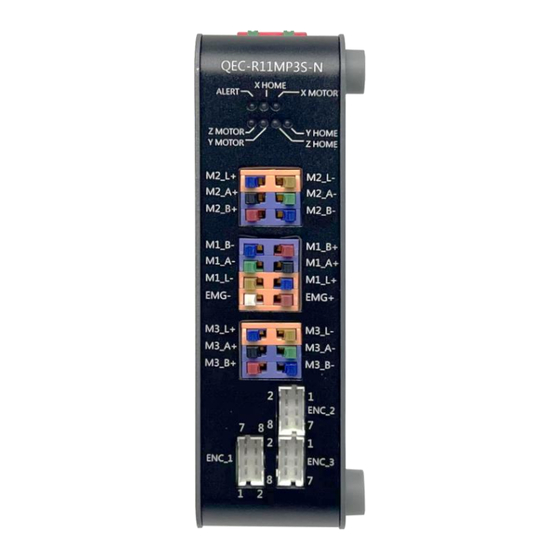
X-Limit (X-Home) signal X MOTOR Green X-axis Motor action signal Y HOME Green Y-Limit (Y-Home) signal Y MOTOR Green Y-axis Motor action signal Z HOME Green Z-Limit (Z-Home) signal Z MOTOR Green Z-axis Motor action signal QEC-RXXMP3S User Manual Ver.1.2 March, 2024... -
Page 21: Drive Motor Connector
M1_L- Brown Limit– switch for Motor 1 M1_L+ Blue +19 to +50VDC Limit+ switch for Motor 1 M3_L+ Blue +19 to +50VDC Limit+ switch for Motor 3 M3_L- Brown Limit- switch for Motor 3 QEC-RXXMP3S User Manual Ver.1.2 March, 2024... - Page 22 Black Input Motor 1 winding A+ M3_A+ Black Input Motor 3 winding A+ M3_A- Green Input Motor 3 winding A- Z-Axis M3_B+ Input Motor 3 winding B+ M3_B- Blue Input Motor 3 winding B- QEC-RXXMP3S User Manual Ver.1.2 March, 2024...
-
Page 23: Encoder Connector
Encoder 1 X-Axis ENC_2 Input Encoder 2 Y-Axis ENC_3 Input Encoder 3 Z-Axis Encoder Pin assignment (ENC_1/ENC_2/ENC_3): Pin# Description ENC_A+ ENC_A- ENC_B+ ENC_B- ENC_C+ ENC_C- Users can see in the side case of QEC-RXXMP3S. QEC-RXXMP3S User Manual Ver.1.2 March, 2024... - Page 24 Pin # Description X_ENCV+ X_ENCV- ENCX-Z+ ENCX-Z- ENCX-B+ ENCX-B- ENCX-A+ ENCX-A- ENC_2 & ENC_3: Description Pin # Pin # Description ENCY-A- ENCY-A+ ENCY-B- ENCY-B+ ENCY-Z- ENCY-Z+ Y_ENCV- Y_ENCV+ ENCZ-A- ENCZ-A+ ENCZ-B- ENCZ-B+ ENCZ-Z- ENCZ-Z+ Z_ENCV- Z_ENCV+ QEC-RXXMP3S User Manual Ver.1.2 March, 2024...
-
Page 25: Dip Switches For Adjustable Current
Piano switches (SW_1: CHP-080A; SW_2 and SW_3: CHP-081A). Switch Specifications: Operating Temperature -40 to +85°C Humidity −10 ~ 65 °C, Relative humidity 0 ~ 96 % Contact resistance 50 mΩ maximum Dimension 12.2 x 5.9 x 4.6 mm Dimension: QEC-RXXMP3S User Manual Ver.1.2 March, 2024... - Page 26 ICOP Technology Inc. Applicable current for 3 types of motors. Users can see in the side case of QEC-RXXMP3S. 1234 STEP MODE 1000 Standby (motor off) 1001 1010 1/2 (A) (0%, 70%, 100%) 1011 7/2 (8) (0%, 100%) 1100 1101...
-
Page 27: Dip Switches Comparison Table
ICOP Technology Inc. 2.2.8 DIP Switches Comparison Table This table is for Ch.2.2.6 Encoder Connector Ch.2.2.7 DIP Switches for Adjustable Current. QEC-RXXMP3S User Manual Ver.1.2 March, 2024... -
Page 28: Din-Rail Installation
ICOP Technology Inc. 2.2.9 DIN-Rail installation Please refer to Ch.3.1 DIN-Rail installation. QEC-RXXMP3S User Manual Ver.1.2 March, 2024... -
Page 29: Wiring To The Connector
2.3 Wiring to the Connector 2.3.1 Connecting the wire to the connector Insulated Terminals Dimensions (mm) Position Ø D1 Ø d1 Ø D2 CN 0.5-6 CN 0.5-8 CN 0.5-10 10.0 2.3.2 Removing the wire from the connector QEC-RXXMP3S User Manual Ver.1.2 March, 2024... -
Page 30: Stepper Motor And Encoder Wiring
For application devices that require position verification and position maintenance, it effectively improves safety and reliability. For information about the 86STEP-577609 stepper motor, please refer to: 86STEP | 86Duino. QEC-RXXMP3S User Manual Ver.1.2 March, 2024... - Page 31 The figure below shows an example of three four-lead, two-phase motors (with encoder) connected to the QEC-RXXMP3S product. The encoder in the QEC-RXXMP3S can read various signals, including A, B, and Z. It's capable of interpreting pulse signals and determining motor rotation direction, CW (clockwise) or CCW (counter clockwise).
-
Page 32: Limit Switches
ICOP Technology Inc. 2.3.4 Limit Switches Limit Switches: 3 x home switch. Digital Input Digital Input channels Input type Sink Voltage level +19 to +50VDC Isolation Voltage Protection 2500 Vrms Application wiring: QEC-RXXMP3S User Manual Ver.1.2 March, 2024... -
Page 33: Emergency Stop
Emergency stop (E-stop) is a safety mechanism used to shut off machinery in an emergency, when it need EMG+ Dark Red +8 to +42VDC to shut down simply and quickly via hardware switch. Application Wiring: QEC-RXXMP3S User Manual Ver.1.2 March, 2024... -
Page 34: 3 Hardware Installation
ICOP Technology Inc. Hardware Installation 3.1 DIN-Rail installation 3.2 Removing QEC-RXXMP Unit QEC-RXXMP3S User Manual Ver.1.2 March, 2024... -
Page 35: Din-Rail Installation
After you mount the QEC-RXXMP, make sure it is locked to the DIN Track. Note: Always turn OFF the Unit power supply and I/O power supply before connecting and removing the QEC-RXXMP. QEC-RXXMP3S User Manual Ver.1.2 March, 2024... -
Page 36: Removing Qec-Rxxmp Unit
Use a flat-blade screwdriver to remove the DIN Track mounting hook on the unit. Pull down and out the flat-blade screwdriver with force against the DIN track until you hear the DIN Track remove the hook. QEC-RXXMP3S User Manual Ver.1.2 March, 2024... -
Page 37: 4 Ethercat Communication
ICOP Technology Inc. EtherCAT Communication 4.1 EtherCAT Basics 4.2 EtherCAT Cabling 4.3 EtherCAT State Machine 4.4 Process Data Object 4.5 CAN application protocol over EtherCAT 4.6 Synchronization Modes QEC-RXXMP3S User Manual Ver.1.2 March, 2024... -
Page 38: Ethercat Basics
EtherCAT uses 4 wires for signal transfer. The pin assignment is compatible with the Ethernet standard (ISO/IEC 8802-3). Color of conductor Signal Description Yellow Transmission Data+ Orange Transmission Data- White RD + Receiver Data+ Blue RD - Receiver Data- QEC-RXXMP3S User Manual Ver.1.2 March, 2024... -
Page 39: Ethercat State Machine
The regular state of each EtherCAT slave after bootup is the OP state. Init After switch-on the EtherCAT slave in the Init state. No mailbox or process data communication is possible. The EtherCAT master initializes sync manager channels 0 and 1 for mailbox communication. QEC-RXXMP3S User Manual Ver.1.2 March, 2024... - Page 40 In the Boot state the slave firmware can be updated. The Boot state can only be reached via the Init state. In the Boot state mailbox communication via the file access over EtherCAT (FoE) protocol is possible, but no other mailbox communication and no process data communication QEC-RXXMP3S User Manual Ver.1.2 March, 2024...
-
Page 41: Process Data Object
3. PDO_InputMapping: Upload read-only parameters (current motor position and speed, Digital Input Level, ADC reading value) to Input PDO. The user can know the time required to upload to Input PDO by reading object 0x1C33.6. QEC-RXXMP3S User Manual Ver.1.2 March, 2024... -
Page 42: Pdo Mapping
0x1620 0x707A 0x00 INT32 0x1620 0x70FF 0x00 INT32 0x1620 0x7060 0x00 INT8 Application Object List: Object Name 0x6040 0x00 Control Word 0x607A 0x00 Target Position 0x60FF 0x00 Target velocity 0x6060 0x00 Mode of Operation QEC-RXXMP3S User Manual Ver.1.2 March, 2024... - Page 43 Position actual value 0x1A20 0x706C 0x00 INT32 Velocity Actual Value 0x1A20 0x70E4 0x01 Additional position encoder value 0x1A20 0x70FD 0x00 UINT32 Digital inputs 0x1A20 0x7061 0x00 INT8 Modes of operation display 0x1A20 0x5024 0x03 ENC Status QEC-RXXMP3S User Manual Ver.1.2 March, 2024...
-
Page 44: Pdo Assign
1C12h is object to assign RxPDO and can assign one object among RxPDO 1600, 1610, or 1620 Objects. ⚫ 1C13h is object to assign TxPDO and can assign one object among TxPDO 1A00, 1A10, or 1A20 Objects. ⚫ QEC-RXXMP3S User Manual Ver.1.2 March, 2024... -
Page 45: Pdo Operation Process
ICOP Technology Inc. 4.4.3 PDO Operation Process For G-code Mode Operation Process: QEC-RXXMP3S User Manual Ver.1.2 March, 2024... - Page 46 ICOP Technology Inc. QEC-RXXMP3S User Manual Ver.1.2 March, 2024...
- Page 47 ICOP Technology Inc. QEC-RXXMP3S User Manual Ver.1.2 March, 2024...
-
Page 48: Can Application Protocol Over Ethercat
(read-only) or variable parameters required for operation, diagnostics, or commissioning. CoE parameters are arranged in a table hierarchy. In principle, the user has read access via the fieldbus. QEC-RXXMP3S supports CAN application protocol over EtherCAT (CoE). EtherCAT Slave structure is as follows. QEC-RXXMP3S User Manual... -
Page 49: Synchronization Modes
ICOP Technology Inc. 4.6 Synchronization Modes Synchronization modes provided by QEC-RXXMP3S are as follows. 4.6.1 Free Run In this mode, the EtherCAT slave device operates independently of the EtherCAT master's timing. The slave does not synchronize its operations with the master's clock or any other synchronization signals in the EtherCAT network. -
Page 50: Distributed Clock
This mode is essential for complex motion control tasks and synchronized operations across multiple devices in an automated system. EtherCAT: Illustration of Distributed Clock (DC). (Source of information: http://www.ethercat.org/) QEC-RXXMP3S User Manual Ver.1.2 March, 2024... -
Page 51: 5 Getting Started
ICOP Technology Inc. Getting Started 5.1 Introduction 5.2 TwinCAT (PP Mode) 5.3 86Duino Coding IDE (PP Mode) 5.4 86Duino Coding IDE (G-code Mode) QEC-RXXMP3S User Manual Ver.1.2 March, 2024... -
Page 52: Notes: Qec's Poe (Power Over Ethernet)
When connecting PoE and non-PoE devices, make sure to disconnect Ethernet cables at pins 4, 5, 7, and 8 (e.g., when a PoE-supported QEC EtherCAT master connects with a third-party EtherCAT slave). QEC’s PoE power supply is up to 24V/3A. QEC-RXXMP3S User Manual Ver.1.2 March, 2024... -
Page 53: Introduction
PC, and the 86Duino IDE, which is compatible with the QEC Master Series. In the following pages, we will walk you through the steps for connecting your QEC-RXXMP3S and initiating your journey toward fully integrating this stepper motor driver into your projects. -
Page 54: Add The Qec-R11Mp3S To The Project
This section assumes that the TwinCAT software is in Config Mode. 1. Scan for the QEC-RXXMP3S device. Right-click on the EtherCAT adapter that the QEC-RXXMP3S is attached to. In the drop-down menu that opens, select the “Scan Device” or “Scan” option. - Page 55 4. Choose “No” when TwinCAT asks you to activate Free Run. We need to set up the PP mapping to the PDO before operation. 5. The QEC-R11MP3S will appear in the device tree and the name will typically begin with “Box”. QEC-RXXMP3S User Manual Ver.1.2 March, 2024...
-
Page 56: Start To Configure The Qec-R11Mp3S
The original check boxes in the "PDO Assignment (0x1C12):" field are 0x1600, 0x1610, and 0x1620. The default check settings are is used in CSP or CSV mode. 2. Change the checked items to 0x1604, 0x1614, and 0x1624, which modify the Outputs PDO Mapping to suit PP mode. QEC-RXXMP3S User Manual Ver.1.2 March, 2024... - Page 57 "PDO Assignment (0x1C13):" column is 0x1A00, 0x1A10, 0x1A20, and the default check setting is used in CSP or CSV mode. 4. Change the checked items to 0x1A04, 0x1A14, and 0x1A24, which modify the Inputs PDO Mapping to suit PP mode. QEC-RXXMP3S User Manual Ver.1.2 March, 2024...
- Page 58 5. After setting, click "Reload I/O Devices (F4)," marked in red in the picture below, to update the PDO Mapping settings. After clicking, a window will pop up asking whether to "Activate Free Run." Please click "Yes." QEC-RXXMP3S User Manual Ver.1.2 March, 2024...
-
Page 59: Control The Qec-R11Mp3S
Click the "Online" page of "Controlword" and click the "Write..." button. Enter 6 in the pop-up window to change the value of Controlword to 6. 2. Then, enter 7 in the pop-up window to change the value of Controlword to 7. QEC-RXXMP3S User Manual Ver.1.2 March, 2024... - Page 60 4. Next, select the BOX 1(QEC-R11MP3S) in the left window. Click the "CoE - Online" page to view all objects and perform Mailbox transmission. Find object 0x6060 and double-click the object with the left mouse button. QEC-RXXMP3S User Manual Ver.1.2 March, 2024...
- Page 61 5. Enter 1 in the pop-up window to set the value of object 0x6060 to 1, and specify the operation mode to Profile Position (PP) mode. 6. Expand "X Axis RxPdoMapping4" and click "Target position", click "Write..." on the "Online" page and enter the position command 32000. QEC-RXXMP3S User Manual Ver.1.2 March, 2024...
- Page 62 ICOP Technology Inc. 7. Set Profile velocity to 6400. 8. Set Profile acceleration to 6400. QEC-RXXMP3S User Manual Ver.1.2 March, 2024...
- Page 63 10. When the New set-point bit changes from 0 to 1, MP3S will receive the new Target position, Profile velocity, and Profile acceleration commands. Therefore, when the motor rotates to the target position, the Controlword must be set to 0x000F to make the New set-point Bit is 0. QEC-RXXMP3S User Manual Ver.1.2 March, 2024...
-
Page 64: 86Duino Coding Ide (Pp Mode)
Here, we'll guide you through the key steps to get your QEC-R11MP3S up and running with the 86Duino IDE. We will show you how to use the EtherCAT Master QEC-M-01P and the QEC-RXXMP3S Series (EtherCAT Slave, 3-axis Stepper Motor Controller). We will be operating CiA402 Profile Position (PP) mode. -
Page 65: Download Software
After downloading, please unzip the downloaded zip file, no additional software installation is required, just double-click 86duino.exe to start the IDE. *Note: If Windows displays a warning, click Details once and then click the Continue Run button once. 86Duino Coding IDE 500+ looks like below. QEC-RXXMP3S User Manual Ver.1.2 March, 2024... -
Page 66: Connect To Your Pc And Set Up The Environment
5. Select the correct board: In the IDE's menu, select Tools> Board > QEC-M-01 (or the QEC-M master model you use). 6. Select Port: In the IDE's menu, select Tools > Port and select the USB port to connect to the QEC-M master (in this case, COM4 (QEC)). QEC-RXXMP3S User Manual Ver.1.2 March, 2024... -
Page 67: Development Method 1: Write Code
// Start the EtherCAT Master. If successful, all slaves enter OPERATIONAL state // Sync Mode, and the parameter 500000 sets the cycle time in nanoseconds EcatMaster.start(1000000, ECAT_SYNC); // Enable motor (CiA402 state set to OPERATION_ENABLED) motor.driveEnable(); QEC-RXXMP3S User Manual Ver.1.2 March, 2024... - Page 68 3: if (motor.profilePositionBegin(0, 10000, 10000) == 0) { pp_state++; break; case 4: if ((motor.driveGetControlword() & (1 << 4)) == 0) { pp_state++; break; case 5: if (motor.driveIsTargetReached()) { pp_state = 0; break; QEC-RXXMP3S User Manual Ver.1.2 March, 2024...
- Page 69 EcatMaster.start(1000000, ECAT_SYNC); // Enable motor (CiA402 state set to OPERATION_ENABLED) motor.driveEnable(); void loop() { switch (pp_state) case 0: // Profile Position Mode Begin. profilePositionBegin(pos, vel, acc); if (motor.profilePositionBegin(81920, 10000, 10000) == 0) { pp_state++; break; QEC-RXXMP3S User Manual Ver.1.2 March, 2024...
- Page 70 The program will run when the upload is complete. After the upload is complete, you can see the motor move to the specified position and then return to the initial position. This process will repeat continuously. QEC-RXXMP3S User Manual Ver.1.2 March, 2024...
-
Page 71: Development Method 2: Use 86Eva With Code
The 86EVA tool can be opened via the following buttons. Once you have confirmed that the correct COM port has been selected of QEC-M-01P, press the Connect button to start scanning the EtherCAT network. QEC-RXXMP3S User Manual Ver.1.2 March, 2024... - Page 72 Press twice on the image of the QEC-M-01 to see the parameter settings. This example will use the default settings and not change any settings; please click "Back" in the upper left corner to return. QEC-RXXMP3S User Manual Ver.1.2 March, 2024...
- Page 73 Port1" from the dropdown menu for M1 in the "Servo Mapping". After finishing, click "Back" in the upper left corner to return. This action sets the M1 (first-axis motor) of the QEC-R11MP3S to be the Virtual Servo Port1 of the EVA. QEC-RXXMP3S User Manual Ver.1.2 March, 2024...
- Page 74 Once you've set your device's parameters, go back to the home screen and press the "Code Generation" button in the bottom right corner. When you're done, double-click the OK button to turn off 86EVA, or it will close in 10 seconds. QEC-RXXMP3S User Manual Ver.1.2 March, 2024...
- Page 75 Additional note: After 86EVA generates code, the following code will be automatically generated in the main program (.ino), and any of them missing will cause 86EVA not to work. : Include EVA Header file #include “myeva.h” ; : Initialize the EVA function EVA.begin() in setup() QEC-RXXMP3S User Manual Ver.1.2 March, 2024...
- Page 76 (VirtualServo1.cia402GetServo()->profilePositionBegin(81920, 10000, 10000) == 0) { pp_state++; break; case 1: // Check if the motor's control word is ready for next command if ((VirtualServo1.cia402GetServo()->driveGetControlword() & (1 << 4)) == 0) pp_state++; break; case 2: QEC-RXXMP3S User Manual Ver.1.2 March, 2024...
- Page 77 After the upload is complete, you can see the motor move to the specified position and then return to the initial position. This process will repeat continuously. For more information and sample requests, please write to info@icop.com.tw, call your nearest ICOP branch, or contact our official global distributor. QEC-RXXMP3S User Manual Ver.1.2 March, 2024...
-
Page 78: 86Duino Coding Ide (G-Code Mode)
5.4 86Duino Coding IDE (G-code Mode) In this section, we will show you how to use the EtherCAT Master QEC-M-01P and the QEC-RXXMP3S Series (EtherCAT Slave, 3-axis Stepper Motor Controller). We will be operating G-code mode. We use the same software and hardware with 5.3 86Duino Coding IDE (PP... - Page 79 // Move back to position X=0 at speed F=10000. This command returns the machine axis to the starting position // at a faster feed rate of 10000. This operation is quicker due to the higher feed rate. QEC-RXXMP3S User Manual Ver.1.2 March, 2024...
- Page 80 1000, after which the program pauses for 6 seconds to ensure the action is completed. Then, the X-axis returns to position 0 at a speed of 10000, and the program pauses for 1 second to ensure the action is completed. This process will continuously repeat. QEC-RXXMP3S User Manual Ver.1.2 March, 2024...
-
Page 81: Development Method 2: Use 86Eva With Code
The 86EVA tool can be opened via the following buttons. Once you have confirmed that the correct COM port has been selected of QEC-M-01P, press the Connect button to start scanning the EtherCAT network. QEC-RXXMP3S User Manual Ver.1.2 March, 2024... - Page 82 Press twice on the image of the QEC-M-01 to see the parameter settings. This example will use the default settings and not change any settings; please click "Back" in the upper left corner to return. QEC-RXXMP3S User Manual Ver.1.2 March, 2024...
- Page 83 Please note the "Device Mode" field in "General," which has two options: CiA-402 Servos and G-code Machine. This example uses the G-code Machine mode. Continue to navigate down to the "Machine Mapping" section. Here, we will select "VirtualCNC Controller1" from the dropdown menu for "X/Y/Z". QEC-RXXMP3S User Manual Ver.1.2 March, 2024...
- Page 84 Once you've set your device's parameters, go back to the home screen and press the "Code Generation" button in the bottom right corner. When you're done, double-click the OK button to turn off 86EVA, or it will close in 10 seconds. QEC-RXXMP3S User Manual Ver.1.2 March, 2024...
- Page 85 Additional note: After 86EVA generates code, the following code will be automatically generated in the main program (.ino), and any of them missing will cause 86EVA not to work. : Include EVA Header file #include “myeva.h” ; : Initialize the EVA function EVA.begin() in setup() QEC-RXXMP3S User Manual Ver.1.2 March, 2024...
- Page 86 1000, after which the program pauses for 6 seconds to ensure the action is completed. Then, the X-axis returns to position 0 at a speed of 10000, and the program pauses for 1 second to ensure the action is completed. This process will continuously repeat. QEC-RXXMP3S User Manual Ver.1.2 March, 2024...
-
Page 87: 6 Slave Information
ICOP Technology Inc. Slave Information 6.1 ESI (EtherCAT Slave Information) file 6.2 Object Dictionary QEC-RXXMP3S User Manual Ver.1.2 March, 2024... -
Page 88: Esi (Ethercat Slave Information) File
0x1000, 0x1001, 0x1008, 0x1009, 0x100a, 0x1010, 0x1011, 0x1018, 0x10F0, 0x10F1, 0x10F3, 0x1c00, 0x1c32, 0x1c33 Entries less or equal one 8Bit shall not overlap byte borders. Entries greater 8Bit shall always start at an exact word border. QEC-RXXMP3S User Manual Ver.1.2 March, 2024... -
Page 89: Standard Objects
QEC-R11MP3S with PoE QEC-R11MP1S Index 1009 Hardware version Index Name Data type Flags Default 1009 Hardware version STRING n.a. Index 100A Software version Index Name Data type Flags Default 100A Software version STRING 5.12 QEC-RXXMP3S User Manual Ver.1.2 March, 2024... - Page 90 0x00000001 (1) 10F1:02 Sync Error Counter Limit UINT32 0x0004 (4) Index 10F8 Timestamp Object Index Name Data type Flags Default 10F8 Timestamp Object UINT64 RW P 9E 04 CA F3 20 00 00 00 QEC-RXXMP3S User Manual Ver.1.2 March, 2024...
-
Page 91: Rxpdo Mapping Objects
SubIndex 001 UINT32 0x6040:00, 16 Map control word. 1604:02 SubIndex 002 UINT32 0x607A:00, 32 Map target position. 1604:03 SubIndex 003 UINT32 0x6081:00, 32 Map profile velocity. 1604:04 SubIndex 004 UINT32 0x6083:00, 32 Map profile acceleration. QEC-RXXMP3S User Manual Ver.1.2 March, 2024... - Page 92 SubIndex 001 UINT32 0x6840:00, 16 Map control word. 1614:02 SubIndex 002 UINT32 0x687A:00, 32 Map target position. 1614:03 SubIndex 003 UINT32 0x6881:00, 32 Map profile velocity. 1614:04 SubIndex 004 UINT32 0x6883:00, 32 Map profile acceleration. QEC-RXXMP3S User Manual Ver.1.2 March, 2024...
- Page 93 SubIndex 001 UINT32 0x7040:00, 16 Map control word. 1624:02 SubIndex 002 UINT32 0x707A:00, 32 Map target position. 1624:03 SubIndex 003 UINT32 0x7081:00, 32 Map profile velocity. 1624:04 SubIndex 004 UINT32 0x7083:00, 32 Map profile acceleration. QEC-RXXMP3S User Manual Ver.1.2 March, 2024...
- Page 94 Index 1632 G code RX PDO Mapping2 Index Name Data type Flags Default Description 1632:0 G code RxPdoMapping2 UINT8 > 1 < For RX PDO mapping number is less than 3. 1632:01 SubIndex 001 UINT32 0x0000:00, 0 Empty QEC-RXXMP3S User Manual Ver.1.2 March, 2024...
-
Page 95: Txpdo Mapping Objects
0x606C:00, 32 Map actual velocity. 1A02:04 SubIndex 004 UINT32 0x60E4:01, 32 Map additional position actual value. 1A02:05 SubIndex 005 UINT32 0x60FD:00, 32 Map digital inputs. 1A02:06 SubIndex 006 UINT32 0x5024:01, 8 Map ENC status. QEC-RXXMP3S User Manual Ver.1.2 March, 2024... - Page 96 0x6864:00, 32 Map actual position. 1A11:03 SubIndex 003 UINT32 0x68E4:01, 32 Map additional position actual value. 1A11:04 SubIndex 004 UINT32 0x68FD:00, 32 Map digital inputs. 1A11:05 SubIndex 005 UINT32 0x5024:02, 8 Map ENC status. QEC-RXXMP3S User Manual Ver.1.2 March, 2024...
- Page 97 Map additional position actual value. 1A20:05 SubIndex 005 UINT32 0x70FD:00, 32 Map digital inputs. 1A20:06 SubIndex 006 UINT32 0x7061:00, 8 Map mode of operation display. 1A20:07 SubIndex 007 UINT32 0x5024:03, 8 Map ENC status. QEC-RXXMP3S User Manual Ver.1.2 March, 2024...
- Page 98 0x7064:00, 32 Map actual position. 1A24:03 SubIndex 003 UINT32 0x70E4:01, 32 Map additional position actual value. 1A24:04 SubIndex 004 UINT32 0x70FD:00, 32 Map digital inputs. 1A24:05 SubIndex 005 UINT32 0x5024:03, 8 Map ENC status. QEC-RXXMP3S User Manual Ver.1.2 March, 2024...
- Page 99 Index 1A32 G code TX PDO Mapping2 Index Name Data type Flags Default Description 1A32:0 G code TxPdoMapping2 UINT8 > 1 < For TX PDO mapping number is less than 3. 1A32:01 SubIndex 001 UINT32 0x0000:00, 0 Empty QEC-RXXMP3S User Manual Ver.1.2 March, 2024...
-
Page 100: Sync Manager Objects
Data type Flags Default 0x1C13:00 TX PDO Assign UINT8 > 3 < CiA-402 Mode G-code Mode 0x1C13:01 SubIndex 01 UINT32 0x1A00 0x1A30 0x1C13:02 SubIndex 02 UINT32 0x1A10 0x1A31 0x1C13:03 SubIndex 03 UINT32 0x1A20 0x1A32 QEC-RXXMP3S User Manual Ver.1.2 March, 2024... - Page 101 0x0000 (0) 1C32:0C Cycle Time Too Small UINT16 0x0000 (0) 1C32:0D Shift Time Too Short 1C32:0E SubIndex 014 1C32:0F SubIndex 015 1C32:10 SubIndex 016 1C32:11 SubIndex 017 1C32:12 SubIndex 018 1C32:20 Sync Error BOOL FALSE QEC-RXXMP3S User Manual Ver.1.2 March, 2024...
- Page 102 0x0000 (0) 1C33:0C Cycle Time Too Small UINT32 0x0000 (0) 1C33:0D Shift Time Too Short 1C33:0E SubIndex 014 1C33:0F SubIndex 015 1C33:10 SubIndex 016 1C33:11 SubIndex 017 1C33:12 SubIndex 018 1C33:20 Sync Error BOOL FALSE QEC-RXXMP3S User Manual Ver.1.2 March, 2024...
-
Page 103: Manufacturer Objects
Index Name Data type Flags Default 5000 SP_Voltage UINT16 0x095A (2394) 5001 SP_Current UINT16 0x0000 (0) 5002 PP_Voltage UINT16 0x0959 (2393) 5003 PP_Current UINT16 0x0017 (23) 5004 Temperature INT16 5005 BoxStatus UINT8 0x00 (0) QEC-RXXMP3S User Manual Ver.1.2 March, 2024... -
Page 104: Motor Objects
MP3S can restore object setting to EEPROM. Write corresponding value to object 0x5012 will initialize EEPROM: 0x1108: initialize common objects ⚫ 0x1104: initialize objects of CiA-402 ⚫ 0x1100: initialize objects of G-code mode ⚫ Index Name Data type Flags Default 5012 Initialize EEPROM UINT16 0x0000 (0) QEC-RXXMP3S User Manual Ver.1.2 March, 2024... - Page 105 ENC Mode UINT8 > 3 < 5020:01 ENC_1 UINT8 0x07 (7) 5020:02 ENC_2 UINT8 0x07 (7) 5020:03 ENC_3 UINT8 0x07 (7) Input signal waveforms: Mode Code MODE_STEP_DIR MODE_CWCCW MODE_AB_PHASE MODE_STEP_DIR_x2 MODE_CWCCW_x2 MODE_AB_PHASE_x2 MODE_AB_PHASE_x2 Any other QEC-RXXMP3S User Manual Ver.1.2 March, 2024...
- Page 106 ICOP Technology Inc. MODE_STEP_DIR MODE_CWCCW MODE_AB_PHASE QEC-RXXMP3S User Manual Ver.1.2 March, 2024...
- Page 107 ICOP Technology Inc. MODE_STEP_DIR_x2 MODE_CWCCW_x2 MODE_AB_PHASE_x2 QEC-RXXMP3S User Manual Ver.1.2 March, 2024...
- Page 108 Pol Z Pol B Pol A Index Name Data type Flags Default 5022:0 ENC Control Byte UINT8 > 3 < 5022:01 ENC_1 UINT8 0x0F (15) 5022:02 ENC_2 UINT8 0x0F (15) 5022:03 ENC_3 UINT8 0x0F (15) QEC-RXXMP3S User Manual Ver.1.2 March, 2024...
- Page 109 [6 – 2] IDX-Reset Reserved PCNT-OV PCNT-UV Index Name Data type Flags Default 5024:0 ENC Status UINT8 > 3 < 5024:01 ENC_1 UINT8 0x80 (128) 5024:02 ENC_2 UINT8 0x80 (128) 5024:03 ENC_3 UINT8 0x80 (128) QEC-RXXMP3S User Manual Ver.1.2 March, 2024...
- Page 110 Writing object 0x5025 would set encoder value to writing value. Additional position encoder value (0x60E4/0x68E4/ 0x70E4) would be updated to the same value. Index Name Data type Flags Default 5025:0 ENC Write UINT8 > 3 < 5025:01 ENC_1 INT32 5025:02 ENC_2 INT32 5025:03 ENC_3 INT32 QEC-RXXMP3S User Manual Ver.1.2 March, 2024...
- Page 111 String Segment Number: String Segment Number valid values are 1~14. ⚫ Index 0x50D1 G Code string Object for PDO transmission, the object type is string (26 bytes). Index Name Data type Flags Default 50D1 G Code string STRING (26) QEC-RXXMP3S User Manual Ver.1.2 March, 2024...
- Page 112 0x50D1 0x50E0 0x0000 0x0000 0x0001 "G2 X2000000.0 Y2000000.0 " 0x0000 0x0001 "G2 X2000000.0 Y2000000.0 " 0x0001 0x0002 “Z100.0 I2000000.0 J0.0 F1" 0x0001 0x0002 “Z100.0 I2000000.0 J0.0 F1" 0x0002 0x0103 “536.0” 0x0002 0x0103 “536.0” 0x000F QEC-RXXMP3S User Manual Ver.1.2 March, 2024...
- Page 113 Min of X axis INT64 50D5:02 Max of X axis INT64 50D5:03 Min of Y axis INT64 50D5:04 Max of Y axis INT64 50D5:05 Min of Z axis INT64 50D5:06 Max of Z axis INT64 QEC-RXXMP3S User Manual Ver.1.2 March, 2024...
- Page 114 Object used to control the state of G Code Controller. The object type is UINT8, 0: Servo Off, 1: Servo On. When Servo Off, it cannot receive G code and cannot execute and return to Home. [7 – 4] Reserved Reserved Reserved Reserved Servo On/Off QEC-RXXMP3S User Manual Ver.1.2 March, 2024...
- Page 115 Object used to control the status of G Code Controller. The object type is UINT8. Changing the object to 4 will execute the software EmgStop. Restoring the object to 0 will not clear EmgStop. Clear EmgStop must be executed. [7 – 4] Reserved Reserved Emergency Stop Reserved Reserved QEC-RXXMP3S User Manual Ver.1.2 March, 2024...
- Page 116 G Code string also does not contain Feed-rate, G Code Controller will use the setting of the object Default Feedrate as Feed-rate. ; The unit of Default Feedrate is mm per minute, and the object data type is REAL64. QEC-RXXMP3S User Manual Ver.1.2 March, 2024...
- Page 117 If position limit is enabled, when motor reaches position limit(0x50D5), motor will stay at limit position. Setting object 0x50DD can enable/disable position limit: 0: disable position limit ⚫ 1: enable position limit ⚫ Index Name Data type Flags Default 50DD Enable Position Limit UINT8 0x01 (1) QEC-RXXMP3S User Manual Ver.1.2 March, 2024...
- Page 118 If the String Segment Counter is n (0~13), the String Segment Number must be n+1 for the Controller to receive the new string. String Segment Number Sting Segment Counter Action n + 1 Receive string to FIFO Any other Skip QEC-RXXMP3S User Manual Ver.1.2 March, 2024...
- Page 119 0x50D1 0x50E0 0x0000 0x0000 0x0001 "G2 X2000000.0 Y2000000.0 " 0x0000 0x0001 "G2 X2000000.0 Y2000000.0 " 0x0001 0x0011 "G1 X2000000.0 Y2000000.0 " 0x0001 0x0011 "G1 X2000000.0 Y2000000.0 " 0x0031 0x0112 “F1500.0” 0x0011 0x0112 “F1500.0” 0x001F QEC-RXXMP3S User Manual Ver.1.2 March, 2024...
- Page 120 EmgStop input pins. Status, the X in the table indicates that the object can be any value: Machine State EmgStop Input 0x50D9 0x50D8 0x50D7 Hardware Emergency Stop Software Emergency Stop Servo Off Servo On Homing QEC-RXXMP3S User Manual Ver.1.2 March, 2024...
- Page 121 Index 0x50E3 Limit Inputs Display the pin status of XYZ three-axis Limit inputs. Index Name Data type Flags Default 50E3 Limit Inputs UINT8 0x00 (0) [7 – 3] Reserved Z limit Y limit X limit QEC-RXXMP3S User Manual Ver.1.2 March, 2024...
- Page 122 Writing to the Device Profile (0x50FC) after booting will only change the address content of the SPI ROM where the Device Profile is stored. The results of Servo mode and reading the Device Profile will not change. QEC-RXXMP3S User Manual Ver.1.2 March, 2024...
- Page 123 MP3S supports receiving G-code via mailbox. Writing G-code string to object 0x50FF instructs MP3S to execute this G-code when Servo-On. String length should be less than 63 characters. Index Name Data type Flags Default 50FF G Code command STRING (64) QEC-RXXMP3S User Manual Ver.1.2 March, 2024...
-
Page 124: Especial Objects (0X6000-0Xffff)
Index 0x605E Fault reaction option code Index Name Data type Flags Default 605E Fault reaction option code UINT16 Index 0x6060 Modes of operation Index Name Data type Flags Default 6060 Modes of operation UINT8 QEC-RXXMP3S User Manual Ver.1.2 March, 2024... - Page 125 UINT32 2000000000 Index 0x607E Polarity Index Name Data type Flags Default 607E Polarity UINT8 0x00 (0) Index 0x6080 Max motor speed Index Name Data type Flags Default 6080 Max motor speed UINT32 0x0000012C (300) QEC-RXXMP3S User Manual Ver.1.2 March, 2024...
- Page 126 Index 0x608B Velocity notation index Index Name Data type Flags Default 608B Velocity notation index UINT8 Index 0x608C Velocity dimension index Index Name Data type Flags Default 608C Velocity dimension index UINT8 0xA4 (164) QEC-RXXMP3S User Manual Ver.1.2 March, 2024...
- Page 127 With methods 19 and 20 (equivalent to methods 3 and 4), the left switching edge of the home switch is used as reference: With methods 21 and 22 (equivalent to methods 5 and 6), the right switching edge of the home switch is used as reference: QEC-RXXMP3S User Manual Ver.1.2 March, 2024...
- Page 128 > 2 < 6099:01 Speed for searching switch UINT32 0x00000001 (1) 6099:02 Speed for searching zero UINT32 0x00000001 (1) Index 0x609A Homing acceleration Index Name Data type Flags Default 609A Homing acceleration UINT32 0x00000001 (1) QEC-RXXMP3S User Manual Ver.1.2 March, 2024...
- Page 129 Data type Flags Default Touch probe position 1 positive 60BA UINT32 value Index 0x60BB Touch probe position 1 negative value Index Name Data type Flags Default Touch probe position 1 negative 60BB UINT32 value QEC-RXXMP3S User Manual Ver.1.2 March, 2024...
- Page 130 Motor resolution UINT32 0x00000C80 (3200) Index 0x60FD Digital inputs Index Name Data type Flags Default 60FD Digital inputs UINT32 0x00000000 (0) Index 0x60FF Target velocity Index Name Data type Flags Default 60FF Target velocity UINT32 QEC-RXXMP3S User Manual Ver.1.2 March, 2024...
- Page 131 Name Data type Flags Default 686C Velocity Actual Value UINT32 Index 0x687A Target position Index Name Data type Flags Default 687A Target position UINT32 Index 0x687C Home offset Index Name Data type Flags Default QEC-RXXMP3S User Manual Ver.1.2 March, 2024...
- Page 132 Velocity notation index UINT8 Index 0x688C Velocity dimension index Index Name Data type Flags Default 688C Velocity dimension index UINT8 0xA4 (164) Index 0x6898 Homing method Index Name Data type Flags Default 6898 Homing method UINT8 QEC-RXXMP3S User Manual Ver.1.2 March, 2024...
- Page 133 Data type Flags Default 68BA Touch probe position 1 positive value UINT32 Index 0x68BB Touch probe position 1 negative value Index Name Data type Flags Default 68BB Touch probe position 1 negative value UINT32 QEC-RXXMP3S User Manual Ver.1.2 March, 2024...
- Page 134 0x00000000 (0) Index 0x68FF Target velocity Index Name Data type Flags Default 68FF Target velocity UINT32 Index 0x6D02 Supported drive modes Index Name Data type Flags Default 6D02 Supported drive modes UINT32 0x000001A1 (417) QEC-RXXMP3S User Manual Ver.1.2 March, 2024...
- Page 135 Default 706C Velocity Actual Value UINT32 Index 0x707A Target position Index Name Data type Flags Default 707A Target position UINT32 Index 0x707C Home offset Index Name Data type Flags Default 707C Home offset UINT32 QEC-RXXMP3S User Manual Ver.1.2 March, 2024...
- Page 136 Velocity notation index UINT8 Index 0x708C Velocity dimension index Index Name Data type Flags Default 708C Velocity dimension index UINT8 0xA4 (164) Index 0x7098 Homing method Index Name Data type Flags Default 7098 Homing method UINT8 QEC-RXXMP3S User Manual Ver.1.2 March, 2024...
- Page 137 Data type Flags Default Touch probe position 1 positive 70BA UINT32 value Index 0x70BB Touch probe position 1 negative value Index Name Data type Flags Default Touch probe position 1 negative 70BB UINT32 value QEC-RXXMP3S User Manual Ver.1.2 March, 2024...
- Page 138 0x00000000 (0) Index 0x70FF Target velocity Index Name Data type Flags Default 70FF Target velocity UINT32 Index 0x7502 Supported drive modes Index Name Data type Flags Default 7502 Supported drive modes UINT32 0x000001A1 (417) QEC-RXXMP3S User Manual Ver.1.2 March, 2024...
- Page 139 Maximum number of modules UINT16 If this is your first time running EtherCAT and using a QEC-M master, we recommend that you read Set up the QEC-M-043T for 86Duino to get your project started. QEC-RXXMP3S User Manual Ver.1.2 March, 2024...
-
Page 140: Warranty
All Trademarks appearing in this manuscript are registered trademark of their respective owners. All Specifications are subject to change without notice. © ICOP Technology Inc. 2024 QEC-RXXMP3S User Manual Ver.1.2 March, 2024...
Need help?
Do you have a question about the QEC-RXXMP3S and is the answer not in the manual?
Questions and answers