
Related Manuals for madbeanpedals VFE Switching Board


Summary of Contents for madbeanpedals VFE Switching Board
- Page 1 VFE Switching Board © 2017 madbeanpedals Some images © 2017 VFE Pedals, used with permission 8.7 update: see pg. 7 2.16” W x 1.33” H...
- Page 2 The VFE Switching Board and micro-controller are included with all the VFE projects available from madbeanpedals. This switching scheme employs “soft bypass”, meaning a momentary non-latching SPST foot-switch is used in place of the ubiquitous 3PDT. This offers some advantages: ...
- Page 3 I Give You Infinite Powers The DC Jack inserts into DC9V. Note that the sleeve and tip are flipped since we commonly use center-tip negative power supplies. Power is reverse-polarity protected via D1. It then passes through a 1mH inductor which creates a low pass filter with the C1 decoupler.
- Page 4 Controllers, Coils and Things The 5v tap connects to the micro-controller (IC3: PIC12F509) for power. The relay coil (TQ2-L-5v) connects to pins 3 and 6 on the PIC. Pin4 of the PIC connects to ground via a 1k resistor and momentary switch. When the momentary switch is depressed, the PIC “reads”...
- Page 5 Whar Signal Goes? Whar??!!! You can see from this snippet that the Switching Board utilizes an effect-input grounding scheme. IOW, when the audio circuit is bypassed its input is grounded. Note - The schematic lists the jack as NMJ6HCD2-SM. This is a “sleeve make” jack. When the jack is inserted, it lifts the sleeve to connect to the switched portion of the jack (thus connecting DC ground to the circuit ground).
- Page 6 Jacked Up You should use the jack spec’d in the schematic (linked in the Mouser BOM). It actually doesn’t matter if you use a stereo or mono jack since the ring portion of the stereo jack is not connected to anything. It does, however, require this particular “sleeve make”...
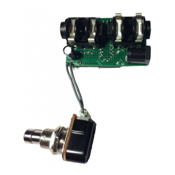
- Page 7 Lock washer soldered to the DC Jack sleeve. For convenience, I have created a MOUSER project for the Switching Board components. It includes ALL options, so be sure to remove the items you don’t need. Note: It does not include the momentary switch. Mouser Project: VFE_SwitchingBoard http://www.mouser.com/ProjectManager/ProjectDetail.aspx?AccessID=b1a505584d 8.7 update: Mouser appears to no longer stock the low-ESR 47uF caps originally listed.
- Page 8 B.O.M. Type Desc. Rating Used With Metal Film 1/2W Metal Film 1//8W Metal Film 1//8W Choral Reef only Metal Film 1//8W Choral Reef only 100k Metal Film 1//8W Metal or Carbon Film 1//8W 100n MLCC 25v min MLCC 16v min 47uF Low ESR Electrolytic 16v min Split Rail, Choral Reef...
- Page 9 Switching Board Schematic...
Need help?
Do you have a question about the VFE Switching Board and is the answer not in the manual?
Questions and answers