
Related Manuals for THORLABS VantagePro QG4


Summary of Contents for THORLABS VantagePro QG4
- Page 1 Class 1 Servo Amplifier For Use With QG4 and QG5 VantagePro® Series Galvo Systems User Guide...
-
Page 3: Table Of Contents
Troubleshooting and Repair ..................14 6.2.1 Finding the Issue ............................... 14 6.2.2 LED Status Indicators ............................14 6.2.3 Slew Rate Limiter (Main Board – J4) ........................15 Chapter 7 Disposal (Required if Relevant) ................... 16 Chapter 8 Thorlabs Worldwide Contacts ..................17... -
Page 4: Chapter 1 Introduction
Introduction Intended Use This manual covers the installation and use of the Thorlabs Class 1 Servo Amplifier Board that accompanies the QG4 and QG5 Galvanometer Systems. This servo amplifier board is intended to control the paired motor with a wide range of loads under a variety of command input conditions. The servo amplifier comes affixed to a mounting bracket for flexible integration into larger systems. - Page 5 Thorlabs.com. When two single-axis galvo systems are to be used as a pair, it becomes necessary to match-tune these as a set. For additional information on purchasing XY Galvo Pairs, please contact Thorlabs Technical Sales Team. Page 2...
-
Page 6: Chapter 2 Technical Data
Class 1 Servo Amplifier for QG4/QG5 Galvos Chapter 2: Technical Data Chapter 2 Technical Data Specifications Item # Inputs Command Input Range ±10 V Position Input Scale Factor 0.67 V/° 0.50 V/° Velocity Command Max 3.61×10 2.98×10 Acceleration Command Max 1.31×10 8.91×10 20 kΩ... - Page 7 Class 1 Servo Amplifier for QG4/QG5 Galvos Chapter 2: Technical Data Performance Graphs Sine Triangle 90/10 Sawtooth Figure 1 QG4X Optical Excursion Angle vs Frequency Sine Triangle 90/10 Sawtooth Figure 2 QG5X Optical Excursion Angle vs Frequency Performance graph details: All waveforms were created using raw waveform generator signals.
- Page 8 Class 1 Servo Amplifier for QG4/QG5 Galvos Chapter 2: Technical Data Mechanical Drawings Figure 3 Class 1 Servo Amplifier Mechanical Drawing Rev. A, May 13, 2024 Page 5...
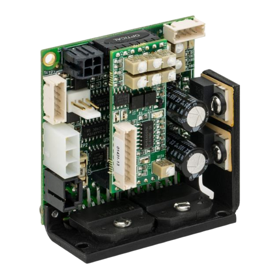
- Page 9 Class 1 Servo Amplifier for QG4/QG5 Galvos Chapter 2: Technical Data Figure 4 Jumpers, Test Points, and LEDs Designator Function 5 A Fuse Galvo PD Ground Lug Command Slew Rate Galvo Coil Power Main Diagnostic Direction Jumper Personality Diagnostic Page 6 MSTN009817-D03...
-
Page 10: Power Connector (Main Board - J7)
Class 1 Servo Amplifier for QG4/QG5 Galvos Chapter 2: Technical Data Figure 5 Reference Designations Reference Points Designator Default State Open Short Open 10 V Command Open Differential Command Single-Ended Command Short External Enable Servo Enabled R141 Open QG4/QG5 R142 Short QG4/QG5 Pin Connections... -
Page 11: Command Input Connector (Main Board - J3)
Class 1 Servo Amplifier for QG4/QG5 Galvos Chapter 2: Technical Data 2.4.2 Command Input Connector (Main Board – J3) Pin Number Function +Command Ground - Command Offset Adjustment a. The external offset adjustment is provided on Pin 4 but is not generally used. This offset is adjusted internally to zero at the factor. -
Page 12: Chapter 3 Safety
Class 1 Servo Amplifier for QG4/QG5 Galvos Chapter 3: Safety Components Figure 1 Components of a QG4 or QG5 Single-Axis Galvo System Figure 2 Location of Servo Amplifier in System Chapter 3 Safety During periods of extended or vigorous use, the temperature of the servo amplifiers can increase. Care should be exercised to avoid contact with the board, mounting bracket, and heat sinks. -
Page 13: Chapter 4 Installation
Class 1 Servo Amplifier for QG4/QG5 Galvos Chapter 4: Installation Although the unit does not emit radiation, it does redirect laser radiation emitted from other devices. Operators must follow all safety precautions provided by the manufacturer of any associated laser devices. Safety precautions should be taken to avoid exposure to laser radiation. -
Page 14: Connect The Servo Amplifier Board To The Galvanometer
<100 mV ripple, <0.5% DC to 30 MHz noise should be used. Switching-style supplies typically exceed acceptable noise levels and are not recommended. Suitable power supply options can be found on Thorlabs.com. 1) Adjust the power supply output to within the proper range. -
Page 15: Ground Connections
Class 1 Servo Amplifier for QG4/QG5 Galvos Chapter 5: Operation 4.3.4 Ground Connections Proper grounding is required for optimal system performance. Due to the susceptibility of galvo systems to electronic noise, the system should have a dedicated power supply to avoid interference entering through the grounding. -
Page 16: Minimum Recommended Daq Specifications
Section 2.4.3. The mating connector is a Molex 51090-0800 connector with (8) Molex 50212-8000 or 50212-8100 pins. The pins should be used with AWG 24-30 wire. A pre-made cable assembly with this connector and fly leads is available for purchase from Thorlabs. Position Output The position output signal (J12, Pin 1) provides a scaled instantaneous position output from the galvanometer that is buffered through an amplifier. -
Page 17: Remote Servo Enable Connector (Main Board - J8)
Class 1 Servo Amplifier for QG4/QG5 Galvos Chapter 6: Troubleshooting and Repair Current Monitor The current signal (J12, Pin 7) is the current that is being sent to the galvanometer coil. This signal is represented as 1V/Amp of current in the coil. High frequencies and large steps result in greater current draw, which results in increased temperature in the system and may require additional thermal management. -
Page 18: Slew Rate Limiter (Main Board - J4)
Class 1 Servo Amplifier for QG4/QG5 Galvos Chapter 6: Troubleshooting and Repair If the green indicator is steady, the system is receiving power to the voltage regulators. If the LED is off or dim, one of the two voltage rails (+ or - supply voltage) is not present. When the servo enters a fault state, the red indicator will illuminate. -
Page 19: Chapter 7 Disposal (Required If Relevant)
Contact Thorlabs for more information. Waste treatment is your own responsibility. “End of life” units must be returned to Thorlabs or handed to a company specializing in waste recovery. Do not dispose of the unit in a litter bin or at a public waste disposal site. It is the user’s responsibility to delete all private data stored on the device prior to disposal. -
Page 20: Chapter 8 Thorlabs Worldwide Contacts
Class 1 Servo Amplifier for QG4/QG5 Galvos Chapter 8: Thorlabs Worldwide Contacts Chapter 8 Thorlabs Worldwide Contacts For technical support or sales inquiries, please visit us at for our most up-to-date www.thorlabs.com/contact contact information. Corporate Headquarters Product Manufacturer Thorlabs, Inc. - Page 22 www.thorlabs.com...
Need help?
Do you have a question about the VantagePro QG4 and is the answer not in the manual?
Questions and answers