
Subscribe to Our Youtube Channel
Related Manuals for THORLABS FSLOPAX1


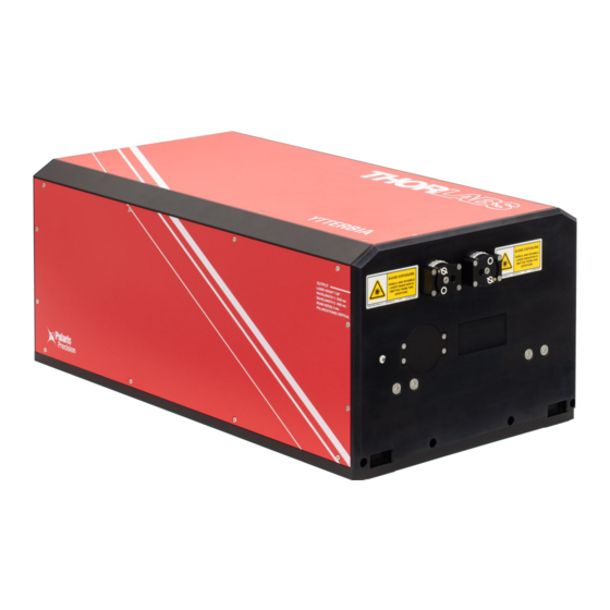
Summary of Contents for THORLABS FSLOPAX1
- Page 1 FSLOPAX1 Ytterbium-Based Femtosecond Optical Parametric Amplifier (OPA) User Guide...
-
Page 2: Table Of Contents
FSLOPAX1 Femtosecond Optical Parametric Amplifier Table of Contents Chapter 1 Safety ......................... 1 1.4.1 Operation ................................5 1.4.2 Safety During Operation ............................5 Chapter 2 Description ......................... 6 Chapter 3 Setup ........................11 Chapter 4 Software Overview ....................15 4.3.1 Laser Amplifier –... - Page 3 FSLOPAX1 Femtosecond Optical Parametric Amplifier Chapter 8 Trouble Shooting ...................... 29 Chapter 9 Configure Network Adapter ..................30 Chapter 10 Certifications and Compliance ................... 33 Chapter 11 Regulatory ........................ 34 Chapter 12 Thorlabs Worldwide Contacts ................... 35...
-
Page 4: Chapter 1 Safety
Explosion Warning This instrument must not be operated in an explosion endangered environment. Laser Warning The FSLOPAX1 laser is a Class IV laser. Avoid Eye or Skin Exposure to Direct or Scattered Radiation. Laser Warning Always wear appropriate laser safety eyewear during laser setup and operation. - Page 5 Class 4 lasers such as the FSLOPAX1 laser may cause damage to the skin, and also to the eye, even from the viewing of diffuse reflections. These hazards may also apply to indirect or non-specular reflections of the beam, even from apparently matte surfaces.
- Page 6 Chapter 1: Safety FSLOPAX1 Femtosecond Optical Parametric Amplifier 15. The unit is supplied with a region-specific power cord. If using your own power cord, make sure it is IEC 320 compatible. 16. Make sure that the line voltage rating marked on the rear panel agrees with your local supply and that the appropriate fuses are installed.
- Page 7 50 to 60 Hz. It draws 10 A maximum. The maximum power consumption is dependent on the operating parameters of the laser system, with a peak power draw of less than 400 W and a typical operational power draw of 100 W. The FSLOPAX1 chiller requires 100/240 VAC, 50/60 Hz, 5 A max. Laser Output Parameters The output parameters for the laser system are outlined in the table below, followed by classification warning labels, shown in Figure 3.
-
Page 8: Operation
FSLOPAX1 Femtosecond Optical Parametric Amplifier 1.4.1 Operation Prior to initializing and operating your FSLOPAX1, please consult the following list to ensure that the unit can be safely operated. 1. Read the user’s manual thoroughly. 2. Inspect the unit for any signs of damage. -
Page 9: Chapter 2 Description
LEDs. In the Simmer state the user can change the repetition rate of the pulse picker. The FSLOPAX1 OPA can provide either a 1035 nm or 1650 nm output beam, which are referred to as “Bypass” and “OPA” operation modes in the software GUI. Please note when operating in the Bypass mode the OPA output is disabled, and vice versa. - Page 10 Chapter 2: Description FSLOPAX1 Femtosecond Optical Parametric Amplifier Figure 4 FSLOPAX1 Laser Head Rev. B, May 1, 2023 Page 7...
- Page 11 FSLOPAX1 Femtosecond Optical Parametric Amplifier Chapter 2: Description Laser Head Front and Rear Panels Figure 5 Laser Head Front Panel Callout Description Aperture Shutter Position Inidicator for Bypass Output Manual Aperture Wheel to Open/Close Shutter for Bypass Output Bypass Output Aperture...
- Page 12 Chapter 2: Description FSLOPAX1 Femtosecond Optical Parametric Amplifier Figure 6 Laser Head Back Panel Callout Description Water In Water Out Fixed Optical Umbilical Mounting Location for Removable Handles (4 Places) USB 2.0 Type-B Connector Sub-D 25 Pin Umbilical to Controller...
- Page 13 FSLOPAX1 Femtosecond Optical Parametric Amplifier Chapter 1: Figure 8 Laser Controller Back Panel Callout Description AC Power On/Off Switch Fuse Tray AC Power Cord Connector USB 2.0 Type-A Connector to Laser Ethernet Port to Computer Oscillator Pulse Train Monitor (BNC Female, 50 Ω, <1 V)
-
Page 14: Chapter 3 Setup
Electronics Setup Once the FSLOPAX1 laser head has been properly secured to the table, it is advised that you take time to route the electric cables and components in order to ensure easy operation of the unit without introducing unnecessary Rev. - Page 15 FSLOPAX1 Femtosecond Optical Parametric Amplifier Chapter 3: Setup hazards to the system. The stainless steel optical umbilical has a minimum bend radius of 150 mm and should be routed carefully. This section will describe the proper installation of the additional system components.
- Page 16 Electronics Unit (Back) – User Connections are Sub-D 25, USB 2.0 Type A, and Ethernet 5. Turn on the FSLOPAX1 Controller via the power switch next to the AC plug on the back of the electronics box (Figure 13). Note it takes ~1.5 minutes for the system to initialize after receiving AC power.
- Page 17 IP address necessary to communicate with the controller are in Chapter 9. 8. Launch the Ytterbia software (downloaded from the Thorlabs website) on the computer and connect to the device. 9. Connect the diagnostic signals (“Pulse Train Monitor” and “Laser Synchronization” in Figure 13 and Figure 14, respectively) as desired: 10.
-
Page 18: Chapter 4 Software Overview
Chapter 4: Software Overview FSLOPAX1 Femtosecond Optical Parametric Amplifier Chapter 4 Software Overview This section covers only the options and controls accessible through the Ytterbia software. Please consult Chapter 5 for actual system operation instruction. Ytterbia Software Figure 15 Ytterbia Software The Ytterbia software gives the user control of the laser while providing system feedback on the system spectra, power levels, and other diagnostics built into the laser system which will be described in detail below. - Page 19 Laser Operation Mode The FSLOPAX1 allows the user to either route the 1035 nm light directly out of the box (Bypass mode) or through the OPA (OPA mode). On start-up the user will need to choose what mode they would like to operate the laser in.
-
Page 20: Laser Amplifier - Bypass Mode
Chapter 4: Software Overview FSLOPAX1 Femtosecond Optical Parametric Amplifier 4.3.1 Laser Amplifier – Bypass Mode This section allows the user to turn on the amplifier and provides information on the amplified 1035 nm power and energy. Figure 18 Laser Amplifier – Bypass Mode Laser Power –... -
Page 21: Laser Amplifier - Opa Mode
FSLOPAX1 Femtosecond Optical Parametric Amplifier Chapter 4: Software Overview 4.3.2 Laser Amplifier – OPA Mode This section allows the user to turn on the amplifier and provides information on the 1650 nm OPA power and energy. Figure 19 Laser Amplifier – OPA Mode Laser Power –... -
Page 22: Chapter 5 System Operation
Chapter 5 System Operation This section details the typical day-to-day operation of the FSLOPAX1 laser. The system is controlled primarily through the software which you can download from the Thorlabs website. If you have questions regarding safe operation of the laser, please contact Thorlabs. - Page 23 FSLOPAX1 Femtosecond Optical Parametric Amplifier Chapter 5: System Operation Figure 21 Connecting to the System 6. The following window (Figure 22) confirms a successful connection to the Laser. Figure 22 Successful Connection to the Laser FSLOPAX1 Start-Up and Tuning 1. Select either Bypass or OPA mode for the laser to operate in. Once selected, the button will turn yellow.
- Page 24 Chapter 5: System Operation FSLOPAX1 Femtosecond Optical Parametric Amplifier Figure 24 Repetition Rate Drop-down 3. Turn the seeder power on by toggling the on/off button. Figure 25 Seeder Power When the seeder is on and the seeder spectrometer is selected, the live seeder spectrum is displayed in white while the reference spectrum is displayed in red.
- Page 25 FSLOPAX1 Femtosecond Optical Parametric Amplifier Chapter 5: System Operation Note that you can choose the wavelength range of the spectrum by changing the minimum and maximum wavelengths located at the bottom of the graph. Figure 27 Changing Wavelength Limits 4. In the Diode Current section, set the diode current to the desired current. Please note that the current limit has been set for each individual repetition rate and will auto-populate when the repetition rate is changed.
- Page 26 Chapter 5: System Operation FSLOPAX1 Femtosecond Optical Parametric Amplifier 8. Verify the 1030 nm power and OPA power outputs read as expected. Figure 32 FSLOPAX1 Parameters FSLOPAX1 Laser Power Down 1. Turn the laser power off. 2. Turn seeder power off.
- Page 27 4. Wait for the “OK to shutdown” to appear on the controller screen. Figure 34 Shut Down Screen 5. Turn off the FSLOPAX1 Controller via the power switch next to the AC plug on the back of the electronics box (Figure 35). Figure 35...
-
Page 28: Chapter 6 Specifications
Chapter 6: Specifications FSLOPAX1 Femtosecond Optical Parametric Amplifier Chapter 6 Specifications Optical Specifications Optical Performance Specifications Output Beam Main Bypass Center Wavelength 1650 ± 5 nm 1035 nm ± 5 nm <220 fs (Typical) Pulse Duration (FWHM) 65 fs (Typical) <250 fs (Max) - Page 29 FSLOPAX1 Femtosecond Optical Parametric Amplifier Chapter 6: Specifications Electrical Specifications Electrical Requirements Input Voltage 100 - 240 V Frequency 50 - 60 Hz Power Consumption Controller 400 W (Max) Power Consumption Chiller 600 W (Max) Laboratory Specifications Environmental Requirements Room Temperature Range 17 °C to 25 °C...
-
Page 30: Chapter 7 Mechanical Drawing
Chapter 7: Mechanical Drawing FSLOPAX1 Femtosecond Optical Parametric Amplifier Chapter 7 Mechanical Drawing Laser Head Laser Controller Rev. B, May 1, 2023 Page 27... - Page 31 FSLOPAX1 Femtosecond Optical Parametric Amplifier Chapter 7: Mechanical Drawing Chiller Page 28 TTN309574-D02...
-
Page 32: Chapter 8 Troubleshooting
2. If the error persists, press the “Reset” button to reinitialize the devices. 3. If the error still persists, take note of the error code and contact Thorlabs for technical support. The error “Master Key Open” is displayed on the software, and the seeder is unable to turn 1. -
Page 33: Chapter 9 Configure Network Adapter
FSLOPAX1 Femtosecond Optical Parametric Amplifier Chapter 9: Configure Network Adapter Chapter 9 Configure Network Adapter 1. If using a USB to Ethernet adapter, connect the device and ensure that it configures properly. If using a network adapter integrated into the PC, for example the Ethernet RJ45 port on your laptop or desktop, it should already be available for configuration. - Page 34 Chapter 9: Configure Network Adapter FSLOPAX1 Femtosecond Optical Parametric Amplifier On the left-hand side, select “Change adapter settings” 6. Select the adapter you wish to configure to connect to the laser. Right click on this adapter and click on “Properties”.
- Page 35 FSLOPAX1 Femtosecond Optical Parametric Amplifier Chapter 9: Configure Network Adapter 7. In the forthcoming menu, click on “Internet Protocol Version 4 (TCP/IPv4)” and then click on Properties. VirtualBox Host-Only Ethernet Adapter 8. Select “Use the following IP Address:” and enter in the IP address entry field, “172.16.1.2”. The Subnet Mask field should default to 255.255.255.0.
-
Page 36: Chapter 10 Certifications And Compliance
Chapter 10: Certifications and Compliance FSLOPAX1 Femtosecond Optical Parametric Amplifier Chapter 10 Certifications and Compliance Rev. B, May 1, 2023 Page 33... -
Page 37: Chapter 11 Regulatory
Waste Treatment is Your Own Responsibility If you do not return an “end of life” unit to Thorlabs, you must hand it to a company specialized in waste recovery. Do not dispose of the unit in a litter bin or at a public waste disposal site. -
Page 38: Chapter 12 Thorlabs Worldwide Contacts
Chapter 12: Thorlabs Worldwide Contacts FSLOPAX1 Femtosecond Optical Parametric Amplifier Chapter 12 Thorlabs Worldwide Contacts For technical support or sales inquiries, please visit us at for our most up-to-date www.thorlabs.com/contact contact information. USA, Canada, and South America UK and Ireland Thorlabs, Inc. - Page 39 www.thorlabs.com...
Need help?
Do you have a question about the FSLOPAX1 and is the answer not in the manual?
Questions and answers