Table of Contents
Advertisement
Quick Links
Advertisement
Table of Contents

Subscribe to Our Youtube Channel
Related Manuals for THORLABS PDFA100


Summary of Contents for THORLABS PDFA100
- Page 1 PDFA100 O-Band Praseodymium Doped Fiber Amplifier Operating Manual...
-
Page 2: Table Of Contents
9.1. Cleaning ......................... 11 9.2. Connector Cleaning ...................... 11 Specifications ........................12 Mechanical Drawings ......................14 Regulatory ...........................15 12.1. Waste Treatment is Your Own Responsibility ............15 12.2. Ecological Background ....................15 Declaration of Conformity ....................16 Thorlabs Worldwide Contacts ..................17 ... -
Page 3: Warning Symbol Definitions
Fiber Amplifier Chapter 1: Warning Symbol Definitions Warning Symbol Definitions Note: Throughout this manual, references to temperature are with respect to °C. Below is a list of warning symbols you may encounter in this manual or on your device. Symbol Description Direct Current Alternating Current... -
Page 4: Safety
Fiber Amplifier Chapter 2: Safety Safety All statements regarding safety of operation and technical data in this instruction manual will only apply when the unit is operated correctly. SHOCK WARNING High voltage inside. To avoid electrical shock, before powering the unit on, make sure that the protective conductor of the 3-conductor power cord is correctly connected to the protective earth contact of the socket outlet. - Page 5 Fiber Amplifier Chapter 2: Safety The unit is supplied with a region-specific power cord. If using your own power cord, make sure it is IEC 320 compatible. Make sure that the line voltage rating marked on the rear panel agrees with your local supply and that the appropriate fuses are installed.
-
Page 6: Description
Chapter 3: Description Description Thorlabs' Praseodymium-Doped Fiber Amplifier (PDFA) offers high gain, high saturation power, and a low noise figure, making it ideal for use within optical networks as either a booster amplifier or preamplifier. The fiber amplifier technology offers an alternative to semiconductor amplifiers (SOAs) with improved optical performance by eliminating the signal distortions typically associated with gain saturation in SOA devices. -
Page 7: Setup
FC bulkhead connector and the patch cable connector beforehand. Please note that a standard single mode (SM) cable should be used for the PDFA100, and that the input power entering the amplifier should not exceed 10 dBm (10 mW). -
Page 8: Operation From Instrument Front Panel
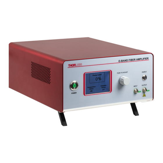
USB Port Communication Port for Diagnostics and Remote Fuse Tray Interface See Section 4.2 for Remote Interlock Input (BNC) replacement details. See page 9 for connection logic. Figure 1 Front and Rear Panels of the Fiber Amplifier (PDFA100) Page 6 TTN190684-D02... -
Page 9: Turning On The Amplifier
Fiber Amplifier Chapter 5: Operation from Instrument Front Panel 5.2. Turning On the Amplifier 1. Please consult with your organization’s laser safety officer regarding proper operation of the amplifier at your institution. LASER WARNING The amplifier generates invisible amplified spontaneous emission (ASE) even without any optical input. -
Page 10: Remote Operation From Command-Line Interface
Fiber Amplifier Chapter 6: Remote Operation from Command-Line Interface Remote Operation from Command-Line Interface The Command Line Interface (CLI) provides the user with a method of controlling the PDFA remotely over the USB interface that is emulating a serial port. A standard terminal program (such as Tera Term) can be used to send commands to the PDFA and receive responses. -
Page 11: Making Safety Interlock Connections
Making Safety Interlock Connections The PDFA100 is equipped with a remote interlock connector located on the rear panel. In order to enable the fiber amplifier, a short circuit must be applied across the terminals of the Remote Interlock connector. This connection is made available to allow the user to connect a remotely actuated switch to the connector (i.e. -
Page 12: Troubleshooting
WARNING Never open the amplifier housing cover for troubleshooting. Refer servicing to qualified personnel. The following table describes some typical problems that may be encountered while using the PDFA100 and possible solutions to these problems. Problem Solution 1. -
Page 13: General Maintenance
Always clean the ferrule end of your fiber patch cables as well as the input and output FC bulkheads prior to inserting the fiber patch cables into the FC bulkheads. Thorlabs offers the FCC-7020 Fiber Cleaning Cloth Spool, which can be used for cleaning the ferrule ends of the patch cables. -
Page 14: Specifications
Specified at 1310 nm. Please refer to published data on the Thorlabs website for typical curves showing the variation of each parameter with wavelength. d. Please refer to published data on the Thorlabs website for the scaling of the output power vs. the input power. - Page 15 Fiber Amplifier Chapter 10: Specifications General Specifications Input Voltage 100 - 240 VAC, 50 - 60 Hz Input Power 20 W (Max) Fuse Rating 2 A, 250 V Fuse Type Time-Lag (Slow-Blow) Fuse Size 5 mm x 20 mm 250.0 mm x 300.0 mm x 122.2 mm Dimensions (W x D x H) (9.84"...
-
Page 16: Mechanical Drawings
Fiber Amplifier Chapter 11: Mechanical Drawings Mechanical Drawings Figure 3 PDFA100 Mechanical Drawing Page 14 TTN190684-D02... -
Page 17: Regulatory
12.1. Waste Treatment is Your Own Responsibility If you do not return an “end of life” unit to Thorlabs, you must hand it to a company specialized in waste recovery. Do not dispose of the unit in a litter bin or at a public waste disposal site. -
Page 18: Declaration Of Conformity
Fiber Amplifier Chapter 13: Declaration of Conformity Declaration of Conformity Page 16 TTN190684-D02... -
Page 19: Thorlabs Worldwide Contacts
Fiber Amplifier Chapter 14: Thorlabs Worldwide Contacts Thorlabs Worldwide Contacts For technical support or sales inquiries, please visit us at www.thorlabs.com/contact for our most up-to-date contact information. USA, Canada, and South America UK and Ireland Thorlabs, Inc. Thorlabs Ltd. sales@thorlabs.com sales.uk@thorlabs.com... - Page 20 www.thorlabs.com...
Need help?
Do you have a question about the PDFA100 and is the answer not in the manual?
Questions and answers