
Subscribe to Our Youtube Channel
Related Manuals for THORLABS EDFA100PX


Summary of Contents for THORLABS EDFA100PX
- Page 1 EDFA100SX, EDFA100PX, EDFA300SX, and EDFA300PX C-Band Fiber Amplifiers - PXIe Plug-in Modules User Guide...
-
Page 2: Table Of Contents
Automatic Current Control (ACC) Mode: ......................10 4.2.2 Automatic Power Control (APC) Mode: ......................10 4.2.3 Automatic Gain Control (AGC) Mode: ....................... 11 Chapter 5 Troubleshooting ......................11 Chapter 6 Disposal ........................11 Chapter 7 Thorlabs Worldwide Contacts ..................12... -
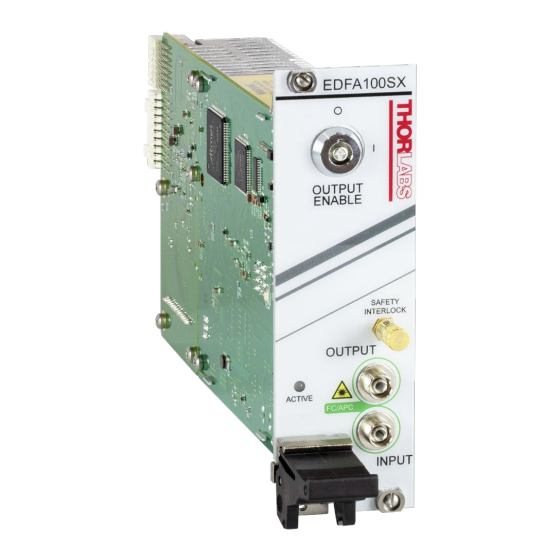
Page 3: Chapter 1 Introduction
(PM): the benchtop systems (Item # EDFA100S / EDFA100P with 20 dBm output power and EDFA300S / EDFA300P with 24.5 dBm output power) and the plug-in PXIe cards (Item # EDFA100SX / EDFA100PX with 20 dBm output power and EDFA300SX / EDFA300PX with 24.5 dBm output power). The benchtop amplifier is built as a stand-alone system with built-in power supply and user interface, while the PXIe module is designed to be operated inside a standard PXIe chassis (not sold by Thorlabs). - Page 4 C-Band Fiber Amplifier Modules Chapter 1: Introduction 28-J9). The EDFA100PX and EDFA300PX PM amplifiers are polarization sensitive, only amplifying light that is linearly polarized along the slow axis of PM FC/APC connector. The input and output fibers of the PM amplifiers are polarization maintaining fiber (PM1550-XP) and the connector keys are aligned to the slow axis of the fibers.
-
Page 5: Technical Data
The wavelength range over which the output power (at 3 dBm input power) does not fall below 18 dBm. b. Specified at 1550 nm. Please refer to published data on Thorlabs’ website for typical curves showing the variation of each parameter. -
Page 6: Absolute Maximum Ratings
The wavelength range over which the small signal gain (at -20 dBm input power) does not fall below 35 dB. b. Specified at 1550 nm. Please refer to published data on Thorlabs’ website for typical curves showing the variation of each parameter with wavelength. -
Page 7: General Specifications
C-Band Fiber Amplifier Modules Chapter 1: Introduction 1.4.3 General Specifications General Specifications Electrical Power (From PXIe Chassis) 12 W (1 A @ 12 V) 128.7 mm x 40.3 mm x 207.2 mm Dimensions (H x W x D) (5.07" x 1.59" x 8.16") Weight 0.45 kg (1 lb) a. -
Page 8: Simplified Declaration Of Conformity
Simplified Declaration of Conformity The full text of the EU declaration of conformity is available at the following internet address: https://www.thorlabs.com/newgrouppage9.cfm?objectgroup_id=10680 FCC Designation Note: This equipment has been tested and found to comply with the limits for a Class B digital device, pursuant to part 15 of the FCC Rules. -
Page 9: Chapter 2 Safety
C-Band Fiber Amplifier Modules Chapter 2: Safety Chapter 2 Safety Laser Warning Avoid Exposure - Radiation Emitted from apertures. Do not look into the laser aperture while the laser is on. Injury to the eye may result. Laser should not be turned on unless there is an optical fiber connected to the laser output port. -
Page 10: Chapter 3 Installation
C-Band Fiber Amplifier Modules Chapter 3: Installation Chapter 3 Installation Warranty Information This precision device is only serviceable if returned and properly packed into the complete original packaging including the complete shipment plus the cardboard insert that holds the enclosed devices. If necessary, ask for replacement packaging. -
Page 11: Chapter 4 Operation
C-Band Fiber Amplifier Modules Chapter 4: Operation Chapter 4 Operation Laser Warning Avoid Exposure – Radiation Emitted from apertures. Do not look into the laser aperture while the laser is on. Injury to the eye may result. Laser should not be turned on unless there is an optical fiber connected to the laser output port. -
Page 12: Mode Of Operation
C-Band Fiber Amplifier Modules Chapter 4: Operation Command Description Returned Value / Command Syntax power Set Power Set-Point (APC Mode) Syntax: Power Power in dBm power? Query Power Set-Point (APC Mode) Returned Value: Power set-point in dBm Set Gain Set-Point (AGC Mode) Syntax: gain gain Gain in dBm... -
Page 13: Automatic Gain Control (Agc) Mode
Contact Thorlabs for more information. Waste treatment is your own responsibility. “End of life” units must be returned to Thorlabs or handed to a company specializing in waste recovery. Do not dispose of the unit in a litter bin or at a public waste disposal site. It is the user’s responsibility to delete all private data stored on the device prior to disposal. -
Page 14: Chapter 7 Thorlabs Worldwide Contacts
C-Band Fiber Amplifier Modules Chapter 7: Thorlabs Worldwide Contacts Chapter 7 Thorlabs Worldwide Contacts For technical support or sales inquiries, please visit us at for our most up-to-date www.thorlabs.com/contact contact information. Corporate Headquarters Product Manufacturer Thorlabs, Inc. Thorlabs, Inc. 43 Sparta Ave... - Page 15 www.thorlabs.com...
Need help?
Do you have a question about the EDFA100PX and is the answer not in the manual?
Questions and answers