Table of Contents
Advertisement
Quick Links
Advertisement
Table of Contents

Subscribe to Our Youtube Channel
Related Manuals for TBB power E4


Summary of Contents for TBB power E4
- Page 1 E4 User Manual...
-
Page 2: Product Introduction
1. Product Introduction This document serves as a user manual for the operation of E4. With this document we aim to provide detailed instructions on the E4 hardware configuration and the system functions, to aid in the understanding of each function module and setting item of the system for the users. -
Page 3: Appearance And Dimensions
1.2 Appearance and Dimensions Structure dimensions Product rendering 1.3 E4 Interface Explanation ① An interface for connecting the Wi-Fi signal antenna ② USB interface for real-time data storage and firmware upgrade. ③ Integrated interface for power supply and communication with the inverter. -
Page 4: Application Scenarios
1.4 Application Scenarios As the core component of the system, E4 plays an important role in human-machine interaction and system energy dispatching control. Through RS485 or CAN communication, E4 can establish communication with the solar hybrid inverter, battery, meter and other components in the system. - Page 5 2. Levels of User Interface The whole system is designed based on the general principle of “system + subsystem”, and each subsystem is in modular design and is independent from each other to ensure a quick respond to the users’ needs as well as smooth evolution of the system. ➢...
-
Page 6: Main Interface
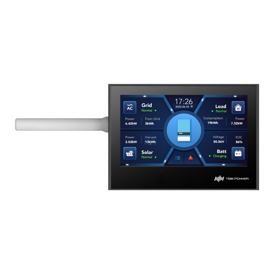
3. Function 3.1 Main Interface The main interface displays basic information of the four major subsystems: AC in, battery, solar and load. It also visually and vividly displays the energy flow in the form of animation. AC in Module Explanation: a) The “Normal”... - Page 7 under normal operation The “Normal” is indicated in gray font in standby status When the module is faulty or disconnected, the status will be indicated as “Abnormal” in red font. b) Power indicates the current power. c) Harvest indicates today's power generation. Battery Module Explanation: a) The “Normal”...
- Page 8 attention of the user and remind the user to attend to the fault.
- Page 9 3.2 AC in Subsystem Items on the left include Total From Grid (total consumption of the grid), Total To Grid (total energy exported to the grid), Running Time (single running time), Total Running Time. Items on the right include the voltage, current, frequency, active power and apparent power of each phase.
-
Page 10: Battery Subsystem
3.3 Battery Subsystem Items on the left include voltage, current, SOC, and the current working status (which could be either charging, discharging or idle) of the battery. Items on the right include the number of battery modules, average cell temperature, total battery capacity, firmware version, voltage and address of high-voltage cell, voltage and address of low-voltage cell, temperature and address of high-temperature cell, temperature and address of low-temperature cell. - Page 11 3.4 Solar Subsystem The solar subsystem includes two parts: PV inverter and MPPT. Items on the left include today's power generation, yesterday's power generation and total power generation; Items on the right include access to the detail page of PV inverter and MPPT.
- Page 12 3.5 Load Subsystem The user can select the Critical Load, Normal Load or Total by clicking the drop-down button. Items on the right include the real-time data of voltage, frequency, current power and total power of each phase.
- Page 13 3.6 Solar Hybrid Inverter After entering the detail page of the solar hybrid inverter, the user can find the current status of the AC in, the load, the solar (MPPT) and the battery, with their real-time voltage, current and power displayed. When there are multiple units in parallel, the user can view the detailed page up and down buttons data of each unit by clicking the With the...
- Page 14 Log, Historical Records and Firmware Upgrade. The Information module records the serial number and firmware version of the E4. The User Log module records all operation logs, and each page displays 5 pieces of records. The Historical Records module records the alarms and faults arising out of the system, and each page displays 5 pieces of records.
-
Page 16: System Setting
The contents of each sub-item, when expanded, are as follows: 1) General Setting Page The user can make basic settings on this page. The screen-on time of the E4 cannot be set to be permanently on, and the maximum screen-on time is up to 999 seconds. - Page 17 Remote Update. Enabling it will allow the user to remotely update the firmware version of E4 and other components of the system. c) Remote Dispatch. Enabling it will allow the user to set parameters via Nova Web or APP.
- Page 18 lead to lock of the inverter. Its normal operation can be restored only after the user clicks the fault unlock button. Delete All Record Data: Clicking this item will delete all running data. 3)System - Electricity Price Setting Set the electricity purchase tariff and feed-in tariff for each time range. 6 time ranges are available for setting.
-
Page 19: System Working Mode
2. System Working Mode a) Selection of working mode ① Zero Export To CT: In this mode, the PV and battery will be preferentially used to supply power to the loads, and the grid will be used to supply power to the loads only when the battery SOC (voltage) reaches its reserved capacity threshold. - Page 20 e) Battery Reserved SOC value Energy Management Matrix(Time of Use). The user can customize 8 time ranges to manage battery charge and discharge. For each time range, the following setting items can be separately configured: using grid to charge battery or not, battery maximum discharge power and battery reserved SOC (or voltage if lead-acid batteries are used).
- Page 21 With regard to grid code, the grid connection standards can be selected through the Grid Code submenu. Currently, only the NRS2017 protocol is available for selection.
- Page 22 4. Solar Setting Two communication protocols are supported with the PV inverter: Solis and Meter. In this page, the user can set the installation location and function of each PV inverter. When the communication protocol is selected as meter, these settings will apply to meter accordingly. Furthermore, user-defined start value, stop value and disconnect value with regard to the frequency shifting are supported to adapt to the frequency shifting of different PV inverter models.
-
Page 23: Load Setting
5. Load Setting The AC OUT 2 on/off can be programmed based on the following setting items. The setting items include: 1. AC OUT2 configuration logic: it can be configured as Smart Load or PV Inverter, which means it can be connected to smart load or PV inverter; 2. - Page 24 6. Switch on PV power>(W) and Switch off PV power <(W): Set the PV power value to trigger the on/off of AC OUT2 . 7. Besides, Time Control option is also available, which allows the user to customize the time range during which the AC OUT 2 will be switched on.
-
Page 25: Battery Setting
6. Battery Setting Battery setting page, where the battery type can be selected. When the battery type is set as the Lithium Battery, its battery capacity is measured and reported by the battery BMS and it is unavailable for setting. Here we need to explain two important technical items: the Negative Offset of Charge Voltage as for the lithium battery and the Temperature Compensation Coefficient as for the lead-acid battery:... - Page 26 temperature. Generally, higher battery temperature will lead to more active chemical reaction, while lower battery temperature will lead to less active chemical reaction in the battery. Therefore, when the battery is in high temperature, the float voltage needs to be decreased to slow down the chemical reaction due to the intensified chemical reaction of the battery;...
-
Page 27: Inverter Setting
7. Inverter Setting There are three types of parallel connection methods available for selection: Stand-alone, Parallel and Three-Phase. The system can automatically detect which parallel connection method is adopted based on the current way of system installation. Number of units in parallel: set the quantity based on the actual number of inverters deployed in the system. -
Page 28: Relay Setting
will be otherwise triggered. Ground Fault Detection: voltage detection between the neutral wire and the ground wire. EPO: Emergency power off. Battery Charging Optimizer: to optimize the battery charging current on the DC side by optimizing the inverter charging waveform. Restart under Protect: to enable or disable the restart after the fault is removed. -
Page 29: Wireless Setting
Through the Wi-Fi configuration, the user can connect to a Wi-Fi network for data exchange between local data and Nova Web & APP. Wi-Fi configuration can be easily made on E4. Currently, the SSID does not support automatic search for nearby Wi-Fi network signals, so it has to be entered manually with the keyboard. -
Page 30: Firmware Upgrade
4.2. Firmware Upgrade With E4, the user can easily upgrade most of the devices in the system with a USB flash drive. Upgrade instructions are provided as follows: 1) Create the [IDM] folder in the root directory of the USB flash drive, and then put the firmware file in the [IDM] folder.
Need help?
Do you have a question about the E4 and is the answer not in the manual?
Questions and answers