Table of Contents
Advertisement
Advertisement
Table of Contents

Subscribe to Our Youtube Channel
Related Manuals for TBB power MPPT


Summary of Contents for TBB power MPPT
- Page 2 MPPT charge controller User Manual...
- Page 3 MPPT charge controller User Manual WARNING: HIGH VOLTAGE INSIDE CAUTION: THE DC FUSE MUST HAVE BEENTURNED OFF BEFORE SERVICING MADE IN CHINA...
- Page 4 General Instruction Thanks for choosing our products and this manual were suitable for Solar Mate series MPPT. This chapter contains important safety and operation instructions. Read and keep this User Guide well for later reference.
-
Page 5: Table Of Contents
MPPT charge controller User Manual 1. General Safety Instruction ......................1 1.1 Safety Instruction........................ 1 1.2 General Precaution ......................1 1.3 Precaution regarding battery operation ................1 2. Instruction ..........................2 2.1 Brief Instruction ........................2 2.1.1 General Description ....................2 2.1.2 Naming Rules ...................... - Page 6 MPPT charge controller User Manual 3.5 Wiring ..........................14 4. Configuration .......................... 16 4.1 Check Before Operation ....................16 4.2 Power ON Test ......................... 16 4.3 Power OFF ........................16 4.4 Setup Wizard ........................16 5. Operation ..........................17 5.1 Menu introduction ......................17 5.2 Initial interface ........................
-
Page 7: General Safety Instruction
MPPT charge controller User Manual 1. General Safety Instruction 1.1 Safety Instruction As dangerous voltage and high temperature exist within the charge controller, only qualified and authorized maintenance personnel are permitted to open and repair it. This manual contains information concerning the installation and operation of the charge controller. -
Page 8: Instruction
2.1 Brief Instruction 2.1.1 General Description Solar Mate is a solar charge controller with built in Maximum Power Point Tracking (MPPT) technology, which can optimize the PV’s output eliminate the fluctuation due to shading or temperatures variables. It tracked the maximum power point of a PV array to deliver the maximum charging current for battery, enabling PV array to increase the output by as much as 30% compared with PWM design. -
Page 9: Structure
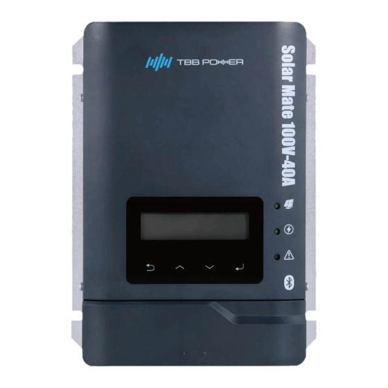
MPPT charge controller User Manual 2.2 Structure 2.2.1 Front Figure 2-1 MPPT charge controller structure in front view Table 2-1 Control Buttons Button Function Cancel the selection. Display the previous level of menu. Display the previous page. ... -
Page 10: Connection Compartment
MPPT charge controller User Manual 2.2.2 Connection compartment External interface terminal as shown in Figure 2-2. Figure 2-2 Connection terminals Table 2-3 Connection terminal introduction Silk-screen Definition Connection terminal for PV array Positive Connection terminal for PV array Negative Connection terminal for Battery Positive Connection terminal for Battery Negative EPO contacts, defined for remote on/off. -
Page 11: Dimension
The MPPT software will continuously adjusts the operating points in an attempt to find the maximum power point of the array no matter how the weather changes. With MPPT, we can maximize the usage of the PV array, increasing the system efficiency by maximum 30%. -
Page 12: Auxiliary Output
MPPT charge controller User Manual 2.3.3 Auxiliary Output The SP has a configurable auxiliary output (relay contact, nominal switching capacity is 2A up to 30VDC), of which can be used for default wake up, or remote switch devices such as alarm . Only one function can be designed at a time. -
Page 13: Comprehensive Protection
MPPT charge controller User Manual battery manufacture are in fact only applied at 20℃-25℃. The BTS (Battery Temperature Sensor) supplied with SP measures the temperature of battery and automatically makes adjustments at real time to properly charge your batteries at the default compensation rate of –... -
Page 14: Equalization Charging (Eq Charging)
MPPT charge controller User Manual Ambient temperature derating curve Figure 2-6 Temperature derating curve Battery over temperature protection During charging, The SP in the process of charging battery temperature real time acquisition, when the battery temperature is too high, it will reduce the charging current and shutdown, and fault warning , in order to prevent thermal runaway of battery. - Page 15 MPPT charge controller User Manual Through this page, you can initiate the desulfuration program manually. After entering this page, please press “ENTER” button to trigger on the EQ charging. Detailed operation, please refer to chapter 5.5 ‘’Para_Battery’’. After 30 minutes, it will quit EQ and enter into float charge.
-
Page 16: Installation And Wiring
MPPT charge controller User Manual 3. Installation and Wiring 3.1 Pre-installation inspection 3.1.1 Check outer packing Please check the outer packing for damage before unpacking, and check the machine model. If there have something wrong, please don’t open it and contact your dealer. -
Page 17: Installation Space Requirements
MPPT charge controller User Manual 3.3.2 Installation space requirements A good ventilation can guarantee the normal operation of equipment. Please always guarantee the enough clearance around SP upon installation. Please refer to following Figure 3-1 for minimum clearance. Figure 3-1 Requirement of minimum clearance 3.3 Installation... -
Page 18: Preparation Before Wiring
MPPT charge controller User Manual 3.4 Preparation Before Wiring 3.4.1 PV Array Preparation Each SP must be connected to its own PV array. Please find following maximum PV array can be connected under various DC systems. Table 3-2 PV allowance for SP... -
Page 19: Cable Preparation
MPPT charge controller User Manual Table 3-3 Breaker Requirement Parts Description Requirement (1) The voltage requirement is greater than 63V. SP100-40 (2) The current requirement is greater than 63A. (1) The voltage requirement is greater than 63V. SP100-20 (2) The current requirement is greater than 32A. -
Page 20: Wiring
MPPT charge controller User Manual 3.5 Wiring Figure 3-3-a Figure 3-3-b Figure3-3 Remove wiring cover plate Step1:Shown as above Figure 3-3-a, by removing wiring cover plate follows the arrow, then you will see as Figure 3-3-b. Table 3-5 toggle switch definition on cover plate... - Page 21 MPPT charge controller User Manual Please refer to following overall wiring diagram of SP as shown in Figure 3-4. Solar Mate BAT- BAT+ BAT+ BAT- PV Array- PV Array+ Battery PV Array Figure 3-4 Wiring diagram of Solar Mate Step2:Please select the appropriate wire according to section 3.4.3.
-
Page 22: Configuration
Step 2: Turn off the circuit breaker between the battery and the MPPT charger 4.4 Setup Wizard Power ON at the first time or after restoring factory settings, the MPPT charger needs to enter the setup wizard to work normally. The user can also reset the Setup Wizard through the Parameter Set interface. -
Page 23: Operation
MPPT charge controller User Manual 5. Operation 5.1 Menu introduction Initial interface Standy interface 1st level menu 2nd level menu 3rd level menu U_PV 69.9V P_Output 800W MCU power on U_BAT 24.9V I_CHG MCU complete initialization ENTER >Running Info T_Inside 54℃... -
Page 24: Initial Interface
MPPT charge controller User Manual 5.2 Initial interface After power-ON, the LCD will have a boot animation of the screen and light the backlight, and then display the following information in sequence. Logo Model Series TBB Power Solar Mate SP100-40 5.3 Real-time information interface... - Page 25 MPPT charge controller User Manual >E_August …… >E_Total >E_MPPT Totally statistic information. Enter to see current error information. Press to scroll through the pages. The first line is the corresponding code for the fault or warning flag. The second line is specific information.
- Page 26 MPPT charge controller User Manual Begin Change the parameters? Press the , a confirmation prompt appears, press the to set the Press the , the cursor appears on default parameter, press to the the right side bit of the parameter.
- Page 27 MPPT charge controller User Manual Display Setting range Description 0- Disable Enable state of charging OutCtrl_CHG 1- Enable external control mode, Default setting: 0-Disable read only. Output dry contact configuration.Select 0, if the connection is detected in the DC Coupling...
- Page 28 MPPT charge controller User Manual Battery type setting. 0- GEL/ OPzV Select 3,5,6 to unlock EQ 1- AGM function. The default 2- Lead-Carbon charging voltage of 3- Flooded different batteries is shown Battery_Type 4- Customerize in Table 5-1. 5- Traction...
- Page 29 MPPT charge controller User Manual Min_Bulk_Time 1~600min Minimum bulk time setting. Default setting:120min Max_Absorp_Time 1~240h Maximum absorption time Default setting:8h setting. 24~2400h Auto_CHG_Cycle Equalization cycle time. Default setting:240h >Para_Battery 0-Disable Charging temperature CHG_T_Compensate 1-Enable compensation coefficient Default setting: 0-Disable -30~0mV/℃(12V) Enable the charging -60~0mV/℃(24V)
-
Page 30: User Control
MPPT charge controller User Manual Table 5-1 Battery charging voltage Charging Battery type Average voltage Float voltage ratio Default setting: 14.1V Default setting:13.7V GEL/OPzV 0.15C Setting range:14.0~14.5V Setting range:13.0~14.0V Default setting: 14.4V Default setting:13.5V 0.15C Setting range:14.0~14.5V Setting range:13.0~14.0V Default setting: 14.1V Default setting:13.5V... -
Page 31: Faq
MPPT charge controller User Manual 6. FAQ 6.1 Fault code Alarm level definition: Fault: MPPT charger failure, into shutdown mode, no more charging. Warning: MPPT charger warning, but also charging normally. Type Name Reason Suggestion Check the string of PV array. - Page 32 MPPT charge controller User Manual and heat dissipation. If the ambient temperature and ventilation is normal, please contact your dealer. PSU_LV Auxiliary power of the PSU_LV_HD charger is too low. The Charger has Please contact your dealer. Sam_HD_Fault sampling failure.
-
Page 33: Specification
MPPT charge controller User Manual 7. Specification SP100-20 SP100-40 SP50-20 SP50-40 Electrical Nominal battery voltage 12/24/48VDC 12/24VDC Maximum charging current 12VDC 294W 588W 294W 588W Maximum Charging 24VDC 588W 1176W 588W 1176W power 48VDC 1176W 2352W 12VDC 300W 600W 300W... - Page 34 MPPT charge controller User Manual...
- Page 35 MPPT charge controller User Manual...
- Page 36 MPPT charge controller User Manual...
Need help?
Do you have a question about the MPPT and is the answer not in the manual?
Questions and answers
I just bought a new camper and they didn’t give me an owners Manuel for it so I don’t have a serial number so how else can I find my serial number