Table of Contents
Advertisement
Advertisement
Table of Contents

Related Manuals for TBB power Solar Mate


Summary of Contents for TBB power Solar Mate
- Page 2 MPPT charge controller User Manual...
- Page 3 General Instruction Thanks for choosing our products and this manual were suitable for Solar Mate series MPPT. This chapter contains important safety and operation instructions. Read and keep this User Guide well for later reference.
-
Page 4: Table Of Contents
MPPT charge controller User Manual Contents Contents 1. General Safety Instruction......................1 1.1 Safety Instruction.........................1 1.2 General Precaution......................1 1.3 Precaution regarding battery operation................1 2. Instruction.............................2 2.1 Brief Instruction........................2 2.1.1 General Description....................2 2.1.2 Naming Rules......................3 2.2 Structure..........................3 2.2.1 Front..........................3 2.2.1 Front 2.2.2 Control panel......................4 2.2.2 Control panel 2.2.3 Connection compartment...................5 2.2.4 Dimension........................6... - Page 5 MPPT charge controller User Manual 3.6 Grounding Connection.......................20 3.7 PV Array Connection......................20 3.8 Battery Connection......................21 3.9 Communication Connection....................22 3.10 Connecting the multiple units...................22 4. Configuration..........................24 4.1 Check Before Operation....................24 4.2 Power ON Test........................24 4.3 Power OFF........................25 4.4 Setup Wizard........................25 4.4 Setup Wizard 5.
-
Page 6: General Safety Instruction
MPPT charge controller User Manual 1. General Safety Instruction 1.1 Safety Instruction As dangerous voltage and high temperature exist within the charge controller, only qualified and authorized maintenance personnel are permitted to open and repair it. This manual contains information concerning the installation and operation of the charge controller. All relevant parts of the manual should be read prior to commencing the installation. -
Page 7: Instruction
2.1 Brief Instruction 2.1.1 General Description Solar Mate is a solar charge controller with built in Maximum Power Point Tracking (MPPT) technology, which can optimize the PV’s output eliminate the fluctuation due to shading or temperatures variables. It tracked the maximum power point of a PV array to deliver the maximum charging current for battery, enabling PV array to increase the output by as much as 30% compared with PWM design. -
Page 8: Naming Rules
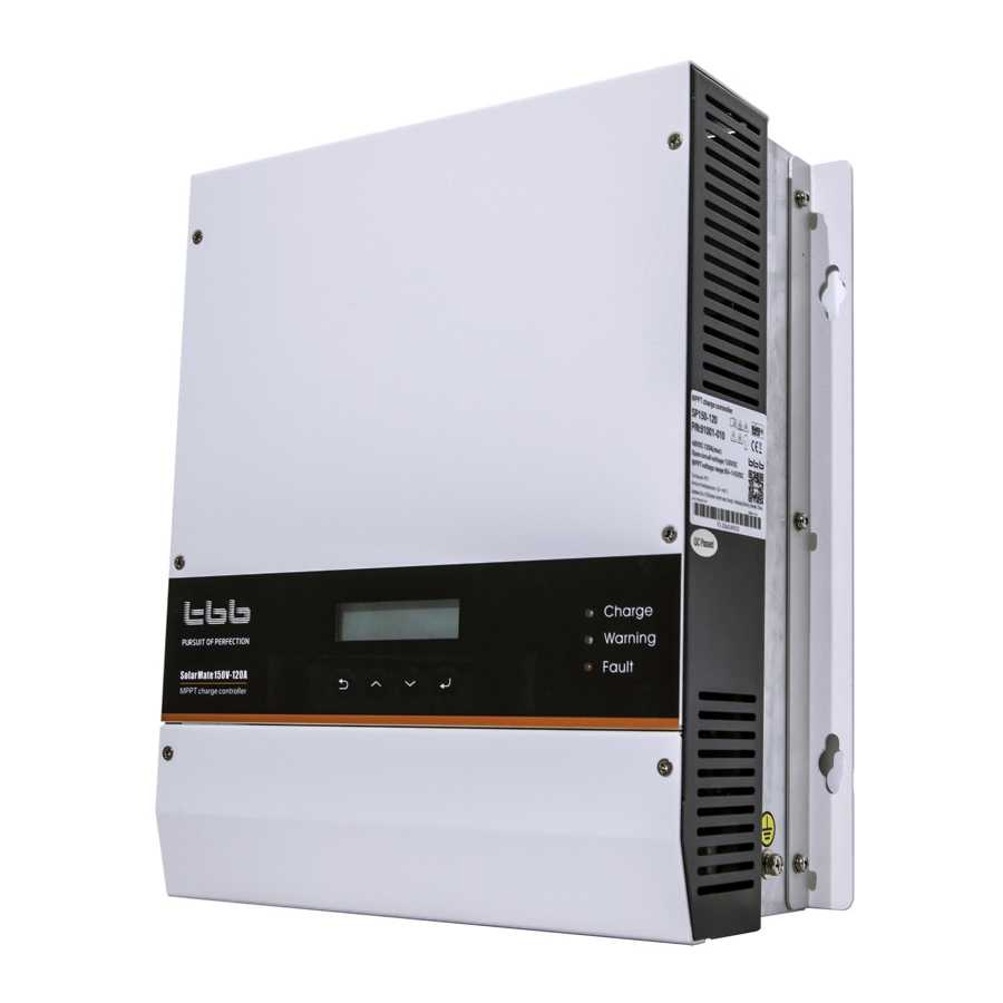
MPPT charge controller User Manual 2.1.2 Naming Rules SPXXX-YYY SP 150-120 Maximum output current PV open circuit voltage Series Field Characte Description SP series MPPT solar charge controller PV open circuit voltage:(V) Maximum output current:(A) 2.2 Structure 2.2.1 Front 2.2.1 Front... -
Page 9: Control Panel
MPPT charge controller User Manual Figure 2-1 MPPT charge controller structure in front view 2.2.2 Control panel 2.2.2 Control panel 2-2 MPPT Control buttons 2-2 MPPT Control buttons 2-1 Control Buttons 2-1 Control Buttons Button Function Button Function Cancel the selection ... - Page 10 MPPT charge controller User Manual Fault It Flash when SP have error.
-
Page 11: Connection Compartment
MPPT charge controller User Manual 2.2.3 Connection compartment External interface terminal as shown in Figure 2-3. Figure 2-3 Connection terminals Table 2-3 Connection terminal introduction Table Silk-screen Definition Com In Connection terminal for parallel communication input. Com Out Connection terminal for parallel communication output. EPO contacts, defined for remote on/off. -
Page 12: Dimension
MPPT charge controller User Manual Pin8 RS485_B 2.2.4 Dimension Figure 2-4 Dimension of Solar Mate MPPT charge controller (SP250-70、SP150-100、SP150-80、SP150-60) - Page 13 MPPT charge controller User Manual Figure 2-5 Dimension of Solar Mate MPPT charge controller( only SP250-100)
-
Page 14: Function
MPPT charge controller User Manual 2.3 Function 2.3.1 Maximum Power Point Tracking The output power of PV array was affected by sun irradiation level and environment temperature. The max power point varies a lot under different weather condition. Max Power Point Tracking allows the maximum harvest of energy from PV array and delivered it into battery. -
Page 15: Tbb Premium Iii Charging Algorithm
MPPT charge controller User Manual 2.3.4 TBB premium III charging algorithm Adaptive charging Adaptive charging Fitted with multistage charging algorithm (bulk-absorption-float-recycle), the TBB premium III charging algorithm is designed to charge battery quickly and fully. Microprocessor controlled charging algorithm with variable absorption charging timer guarantee the optimal charging for batteries of different discharged state. -
Page 16: Comprehensive Protection
MPPT charge controller User Manual Multi battery chemical available Multi battery chemical available Commonly encountered lead acid battery chemicals include AGM, GEL, Traction. The voltage required for a proper charging of different battery varies. SP offer premium charging for above commonly encountered battery categories, of which you can set through the LCD and control button. -
Page 17: Equalization Charging (Eq Charging)
MPPT charge controller User Manual 2.3.6 Equalization Charging (EQ charging) It is strongly recommended to read this section carefully before you start the EQ charging and Don’t leave battery unattended while performing desulfuration. Always check if your battery supplier recommended EQ charging. Only start when it is suitable. - Page 18 MPPT charge controller User Manual Carbon, EQ charging can’t be performed.
-
Page 19: Installation And Wiring
MPPT charge controller User Manual 3. Installation and Wiring 3.1 Pre-installation inspection 3.1.1 Check outer packing Please check the outer packing for damage before unpacking, and check the machine model. If there have something wrong, please don’t open it and contact your dealer. Please check the quantity of accessories, if there have something wrong, please contact your ... -
Page 20: Select Installation Location
Do not install in the place where inflammable and explosive articles are stored. Do not install in the place where children can touch it. Solar Mate MPPT charge controller should be installed in a well-ventilated environment to ensure good heat dissipation. -
Page 21: Installation Angle
MPPT charge controller User Manual 3.3.3 Installation Angle A good ventilation can gurantee the normal operation of equipment. Please vertical or back 15 ° or less installation, for cooling machine. Do not use the charger forward too much, level, upside down, back and side installation Figure 3-2 angle of installation Figure 3-3 angle of installation... -
Page 22: Installation
MPPT charge controller User Manual 3.4 Installation The Solar Mate need to be installed vertically, please choose a flat surface and with 4xM6 supplied to install following Figure 3-4. Install the SP as close to the batteries as possible reducing the voltage drop on cable for the better performance of the equipment. -
Page 23: Preparation Before Wiring
PVB Series PV combiner box is designed for solar off-grid system available with series of MAX VOC 150Vdc and 250Vdc. It can be used between PV Array and Solar Mate series MPPT charge controller. With Built in MC4 connector, fuse, circuit breaker and SPD, it can facilitate the installation as well as improve the system safety. - Page 24 MPPT charge controller User Manual Table 3 -1 PV allowance for SP Solar Mate SP150-120 SP150-80 SP150-60 SP250-100 SP250-70 Applicable PV combiner box PVB150-8 PVB150-6 PVB150-4 PVB250-5 PVB250-3 PV open circuit voltage (Voc) Max. PV short circuit current Maximum charging current (40℃)
-
Page 25: Breaker Preparation
MPPT charge controller User Manual .3 Breaker Preparation .3 Breaker Preparation An over current protection devices DC fuse or DC circuit breaker needs to be installed on positive cable, of which rated for 125% of the nominal rating. The voltage resistance of DC circuit breaker on the battery side should be greater than 63V. -
Page 26: Preparation Before Wiring
MPPT charge controller User Manual Minimum wire size requirements are shown in the Table 3-4 Table 3-4 Recommended DC wiring Recommended DC wiring Model 2 meters 3 meters 5 meters 7 meters 12AWG 4mm² 12AWG 4mm² 10AWG 6mm² 8AWG 10mm² 10AWG 6mm²... -
Page 27: Grounding Connection
MPPT charge controller User Manual ③ ② A B C D ure 3 ure 3 ure 3 ure 3 ure 3 Remove the bottom panel ure 3 Remove the bottom panel 3 -5 Connection terminal Function “BAT+” connection terminal for “BAT+” cable of battery “BAT-”... -
Page 28: Pv Array Connection
MPPT charge controller User Manual Figure 3-8 Grounding terminal Using proper gauges of wires for grounding, recommending 16mm²~35mm². Please connect the SP grounding terminal to the system grounding bar, refer to Figure 3-6 of chapter 3.5.1. Please connect the frame of PV to the system grounding bar, refer to Figure 3-6 of chapter 3.5.1 ... -
Page 29: Battery Connection
MPPT charge controller User Manual screwed. Please install the bottom panel and screw the two screws which are unscrew in chapter3.6. Please double confirm the polarity of PV connection. SP will show fault with reverse polarity connection. 3.8 Battery Connection ... -
Page 30: Communication Connection
MPPT charge controller User Manual 3.9 Communication Connection Please refer to chapter 2.2.3 for port definition. Do not route the communication wire in the same conduit as the DC input/output cable. 3.10 Connecting the multiple units In a multiple unit installation, each SP charge controller need to be connected to a separate PV array. - Page 31 MPPT charge controller User Manual The communication interface of SP series MPPT charge controller must be installed which can be connected with the Kinergier for setting up the DC coupling system. As soon as a communication connection is established, the SP series MPPT charge controller will be controlled by the Kinergier.
- Page 32 MPPT charge controller User Manual...
-
Page 33: Configuration
4. Configuration 4.1 Check Before Operation Please check before Operation according to the following. Solar Mate MPPT charge controller is installed correctly and steady. Reasonable cable layout to meet customer requirements. Make sure the grounding is reliable. -
Page 34: Power Off
MPPT charge controller User Manual 4.3 Power OFF After the MPPT charger is power OFF, there is still residual power and heat in the chassis, which may lead to electric shock or burn. Therefore, after the MPPT charger is powered off for 5 minutes, you should wear protective gloves before removed the MPPT charger. -
Page 35: Operation
3s cycle display in normal Down TBB Power state 2019-03-02 13:26 0 error ENTER ENTER MPPT CHG >Current Error 0 warning CANCEL CANCEL Solar Mate U_PV 115.3V 150V-120A P-Output 5100W 2019-03-02 13:26 Down MPPT Online MPPT Warn: 02 …… ENTER Comm Offline 2019-03-02 10:30... -
Page 36: Initial Interface
Logo Model Series TBB Power Solar Mate SP150-120 Note: In the boot interface, the LCD will establish contact with the Inverter. If there is a communication failure, the communication fault will be displayed. Com error warning... -
Page 37: Information Query Interface
MPPT charge controller User Manual .4 Information query interface .4 Information query interface Press the in the standby interface to enter the 1st level menu. Press the button on the first level menu to enter the corresponding 2nd level menu. Some 2nd level menus can enter the 3rd level menu. - Page 38 2019-04-22 15:31 MPPT Err 09 MPPT Err 09 PSU_LV Enter the interface, you can view the current system information. Solar Mate >Model 150V-120A >Serial Number 0123456789*#@ >System Info >System Info >Software Ver...
-
Page 39: Parameter Setting Interface
MPPT charge controller User Manual 5 Parameter setting interface 5 Parameter setting interface Begin Change the parameters? Press the , a confirmation prompt appears, press the to set the Press the , the cursor appears on default parameter, press to the the right side bit of the parameter. - Page 40 MPPT charge controller User Manual >Parameter Set >Para_System >Para_Battery >Setup Wizard >Clear Para_Mode Change Password Reset Parameter EnergyLog Display Setting range Description Modul parallal address in SYS_Module_Addr 1~4;Default setting:1 system. Enable state of DC >Para_System 0-Disable coupling system mode, 1-Enable read only.
- Page 41 MPPT charge controller User Manual Under the Setting menu, there are three parameter Setting options, among which EQ Setting needs to select the corresponding battery type to open. >Basic Setting >EQ Setting Detail Setting In Basic Setting, there are the following Setting options. Display Setting range Description...
- Page 42 MPPT charge controller User Manual Default setting:14.9V The maximum charging current of the system. Note: This value will be 10~Rate_CHG_CUR (The CHG_MAX_Current changed when changing maximum value is 120A) the battery capacity, and users can reset it with their needs. Min_Bulk_Time 1~600min Minimum bulk time setting.
-
Page 43: User Config
MPPT charge controller User Manual Table 6 -1 Battery charging voltage Battery type Average voltage Float voltage Charging ratio GEL/OPzV 14.1V 13.6V 0.15C 14.4V 13.5V 0.15C Lead-Carbon 14.1V 13.5V 0.20C Flooded 14.7V 13.5V 0.15C Customerize 14.2V(24V) 13.5V 0.20C 13.5V(48V) 13.3V 0.20C Traction 15.2V... -
Page 44: Faq
MPPT charge controller User Manual 6. FAQ 6.1 Fault code Alarm level definition: Fault: MPPT charger failure, into shutdown mode, no more charging. Warning: MPPT charger warning, but also charging normally. Type Name Reason Suggestion Fault Check the string of PV array. - Page 45 MPPT charge controller User Manual Check whether ambient temperature is in range. Check that the charger Temperature inside the T_Board_OT installation environment is charger is too high. well ventilated. If the ambient temperature is too high or is not ventilated well, please improve its ventilation and heat dissipation.
- Page 46 MPPT charge controller User Manual model setting is correct. If the settings are correct, please contact your dealer. BAT_Disconnect_ Battery connection Please check the battery circuit Warning failure. breaker. Heat sink temperature NTC_HS_Fault Please contact your dealer. sampling failure. Check whether ambient temperature is in range.
-
Page 47: Specification
MPPT charge controller User Manual . Specification Model SP150-120 SP150-80 SP150-60 SP250-70 SP250-100 Electrical Nominal battery voltage 24VDC/48VDC ℃ Maximum charging current (40 ) 120A 100A Maximum charging power 6720W 4480W 3360W 3920W 5600W Recommended PV 8000W 5400W 4000W 4400W 6600W PV open circuit voltage (Voc) 150VDC... - Page 48 MPPT charge controller User Manual...
Need help?
Do you have a question about the Solar Mate and is the answer not in the manual?
Questions and answers
How do you change the time and date on the Solar Mate?