Table of Contents
Advertisement
Quick Links
Advertisement
Table of Contents

Subscribe to Our Youtube Channel
Related Manuals for Pulsar Measurement PDFM 6.1


Summary of Contents for Pulsar Measurement PDFM 6.1
- Page 1 PULSAR MEASUREMENT PDFM 6.1 Instruction Manual Manual Rev 1.0...
- Page 2 Note: This page has been left blank intentionally.
-
Page 3: Table Of Contents
PULSAR MEASUREMENT CONTENTS CARRY CASE ........................................4 INTERNAL BATTERY ......................................5 CHARGER ..........................................5 TRANSDUCER CONNECTIONS..................................6 USB-C CONNECTIONS (CHARGER, MODULES) ........................... 6 TRANSDUCER & CABLE ....................................7 KEYPAD..........................................7 POWER ON/OFF & CHARGING .................................. 9 MENU STRUCTURE ......................................10 MESSAGES......................................... -
Page 4: Carry Case
PDFM 6.1 INSTRUCTION MANUAL CARRY CASE The PDFM 6.1 is packaged in an orange IP67 carry case with protective molded foam. The picture below shows how the various components included with the PDFM 6.1 are populated into the molds: Legend... -
Page 5: Internal Battery
CHARGER Included with the PDFM 6.1 package is a mains-powered to USB-C charging adapter rated for 5 Volt & 3 Amp (15 Watt). The power outlet connection type can be changed via the included modular plates. For best results, use the included charger. However, a third-party USB-C cable connected to a third-party charger or battery bank will suffice. -
Page 6: Transducer Connections
When connected to a USB storage device, such as the included flash drive, the PDFM 6.1 becomes the host and will transfer data to the storage device. The design of the PDFM 6.1 allows for future deployment of “modules” which will be able to plug in to the USB-C port on the PDFM, and expand its capability. -
Page 7: Transducer & Cable
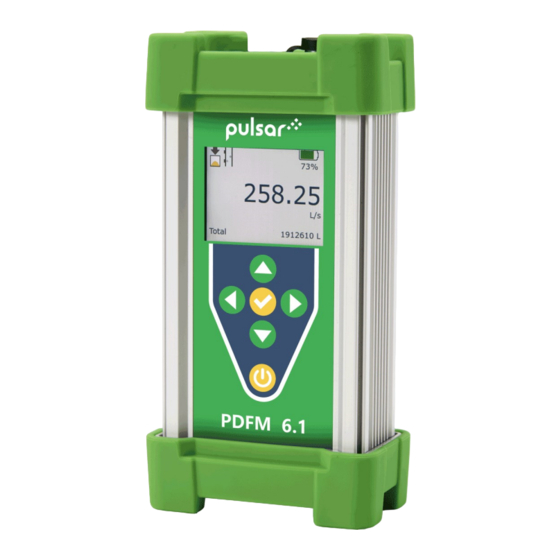
TRANSDUCER & CABLE The PDFM 6.1 is equipped with a single PSE4-A2 transducer which has an integral 12 foot (3.4 meter) cable ready for connection to the PDFM 6.1 socket. The PDFM 6.1 will be “wet” calibrated against a secondary standard for every order. - Page 8 PDFM 6.1 INSTRUCTION MANUAL KEYPAD (CONT.) Keypad layout and functionality continues as shown and described below: CHECK Button: From Main screen – not applicable In programming menus – will move the cursor back one level. Example: if in the Units/Mode sub menu, CHECK will move back to Main Menu.
-
Page 9: Power On/Off & Charging
Press and hold the POWER button for 3-5 seconds to turn the meter on. When powering on, the meter will display a boot-up screen with the Pulsar Measurement logo: When powering off, press the POWER button and the meter will display a pop-up message that asks for input on which power mode to use. -
Page 10: Menu Structure
PDFM 6.1 INSTRUCTION MANUAL MENU STRUCTURE The structure of the menu pages on the PDFM 6.1 is as follows. Using the buttons as shown below will navigate between the different menus: 1 – Inserting a USB drive while on this page will download the 24 hr log data to the USB in .csv format... - Page 11 PULSAR MEASUREMENT MAIN DISPLAY The main display’s top row shows icons for the status of the data logger, signal quality, charging status, battery fuel gauge percentage, and data logging download status when a USB-C drive is inserted while on this page.
-
Page 12: Messages
(no detectable movement of entrained air or solids in the line, or empty pipe). SystemFault indicates a hardware issue, and if you see this message please contact Pulsar Measurement for support. -
Page 13: Password
PULSAR MEASUREMENT STATUS (CONT.) Signal Cutoff - Displays the cutoff where any Signal less than Signal Cutoff will cause the Flow reading to measure 0.0. This value is configurable in the Calibration menu. 24 HR LOG Pressing LEFT from the Main Display will take you to the 24 HR LOG page. -
Page 14: Main Menu
PDFM 6.1 INSTRUCTION MANUAL MAIN MENU Pressing RIGHT from the Main Display (Set Password in Special Functions = 0000) or CHECK from the Password pop-out (Set Password ≠ 0000) will bring you to the Main Menu screen. The Main Menu functions to provide a simple, easy-to-understand starting point to navigate the programming parameters. - Page 15 PULSAR MEASUREMENT UNITS/MODE (CONT.) Flow – Select engineering units for the flow rate on the Main Display and Data Log. Options: Option Description Option Description USG/d liters per day US gallons per day USG/h US gallons per hour liters per hour...
-
Page 16: Calibration
Min Flow – Enter the Min Flow cutoff, which means any flow rate below Min Flow measured by the PDFM 6.1 will result in 0 flow on the display and data log. Default = 4 GPM (0.25 L/s) for a 4 in (100 mm) nominal pipe, which is the approximately equal to 0.1 ft/s (0.03 m/s) flow velocity. -
Page 17: Data Logging
RETRIEVING LOG FILE Plug a USB-C drive (one is included with the PDFM 6.1) into the USB-C port on the bottom the electronics enclosure. The display will show a downloading icon, then a check mark on the icon when the download is complete. -
Page 18: Special Functions
Positive flow will increment the totalizer, and negative flows will decrement the totalizer. Options = No (Default), Yes. Rev. Flow – This parameter enables the flow direction indication on the PDFM 6.1. When flow velocity moves in the direction opposite of the arrow on the transducer, that is negative when Rev. -
Page 19: Configuration
USB-C drive. When prompted on the screen via Insert USB, insert your USB-C drive into the meter, and the PDFM will save the file. Pulsar Measurement technical support will occasionally request this waveform file in order to help diagnose and resolve measurement questions. -
Page 20: Sensor Mounting Location
PDFM 6.1 INSTRUCTION MANUAL SENSOR MOUNTING LOCATION The position of the sensor is one of the most important considerations for accurate flow measurement. The same location guidelines apply to Doppler as they do for most other flow meter technologies. VERTICAL OR HORIZONTAL PIPE - Vertical pipe runs generally provide evenly distributed flow. -
Page 21: Sensor Mounting
PULSAR MEASUREMENT SENSOR MOUNTING Prepare an area 2" wide by 4" long (50mm x 100mm) for sensor bonding by removing loose paint, scale and rust. The objective of site preparation is to eliminate any discontinuity between the sensor and the pipe wall, which would prevent acoustical coupling. - Page 22 Warm temperatures, moisture and vibration will accelerate this process. Super Lube ® as supplied with the DFM 6.1 (and available from Pulsar Measurement or home improvement stores) is recommended for semi-permanent installations.
- Page 23 PULSAR MEASUREMENT SENSOR MOUNTING/COUPLING RECOMMENDATIONS...
-
Page 24: Common Questions And Answers
PDFM 6.1 INSTRUCTION MANUAL COMMON QUESTIONS AND ANSWERS The pipe vibrates. Will it affect the flow meter? Common vibration frequencies are far lower than the sonic frequencies used by the flow meter and will not normally affect accuracy or performance. However, applications where very weak Doppler signal is present (when sensitivity is adjusted to maximum and signal strength is low), accuracy may be affected by pipe vibration, or the flow meter may show readings under no-flow conditions. - Page 25 Does the PDFM 6.1 require periodic recalibration? PDFM 6.1 calibration does not drift over time. The solid-state sensor has no moving parts to wear and affect calibration. The Doppler flow technique generates an ultrasonic signal proportional to the velocity of flow. All timing/counting circuits use crystal-controlled frequency references to eliminate any drift in the processing circuitry.
-
Page 26: Applications Hotline
Obtain an RMA Number from Pulsar Measurement - Before shipping a product to the factory please contact Pulsar Measurement by telephone, fax or email to obtain an RMA number (Returned Merchandise Authorization). This ensures fast service and correct billing or credit. - Page 27 If a product manufactured by Pulsar should prove defective within the first year, return it freight prepaid to Pulsar Measurement along with a copy of your invoice. This warranty does not cover damages due to improper installation or handling, acts of nature, or unauthorized service.
- Page 28 PDFM 6.1 INSTRUCTION MANUAL SPECIFICATIONS General Specifications Liquids containing suspended solids or bubbles minimum size of 100 microns, Operating Parameters: minimum concentration 75 ppm. Flow Rate Range: ±0.03 m/s to 12.2 m/s (±0.1 ft/s to 40 ft/s) in most applications Pipe Size: Ultrasonic sensor mounts on any pipe from 12.7 mm to 4.6 m ID (0.5 in to 15 ft)
- Page 29 PULSAR MEASUREMENT SPECIFICATIONS (Cont.) Transducer Specifications Clamp-on, single-head ultrasonic for pipes from 12.7 mm to 4.6 m ID (0.5 in to 15 ft) Standard Model PSE4-A2: with 3.4 m (12 ft) shielded dual-coaxial cable and latching connector Sensor Mounting Kit: Stainless steel pipe clamp and 3.0 fl oz coupling compound...
-
Page 30: Appendix A - Conversion Table
PDFM 6.1 INSTRUCTION MANUAL APPENDIX A - CONVERSION TABLE CONVERSION GUIDE FROM MULTIPLY BY US GALLONS CUBIC FEET 0.1337 US GALLONS IMPERIAL GALS 0.8327 US GALLONS LITRES 3.785 US GALLONS CUBIC METERS 0.003785 LITRES/SEC 15.85 LITRES CUBIC METERS 0.001 BARRELS... -
Page 31: Appendix B - Pipe Charts
PULSAR MEASUREMENT APPENDIX B - PIPE CHARTS Ductile Ir on Pipe - Standard Classes Size OUTSIDE Clas s Class Class C lass C lass C lass C la ss C EMEN T LIN IN G IN CH D IA. **S TD... - Page 32 PDFM 6.1 INSTRUCTION MANUAL Stainless Steel, Hastelloy "C" & Titanium Pipe Pipe Pipe Scheule 5 S (a) Schedule 10 S (a) Schedule 40 S Schedule 80 S Size O.D. I.D. WALL I.D. WALL I.D. WALL I.D. WALL ½ .840 .710 .065...
- Page 33 PULSAR MEASUREMENT Cast Iron Pipe - ASA Standard Pipe Pipe Class 50 Class 100 Class 150 Class 200 Class 250 Class 300 Class 350 Size O.D. WALL I.D. WALL I.D. WALL I.D. WALL I.D. WALL I.D. WALL I.D. WALL I.D.
- Page 34 10.125 9.701 0.212 10.000 9.812 0.094 12" 12.125 11.315 0.405 12.125 11.565 0.280 12.125 11.617 0.254 www.pulsarmeasurement.com Copyright © 2024 Pulsar Measurement Ltd.. Registered Address: 1 Chamberlain Square CS, Birmingham B3 3AX Registered No.: 3345604 England & Wales Rev 1.0...
Need help?
Do you have a question about the PDFM 6.1 and is the answer not in the manual?
Questions and answers