
Related Manuals for Miller S-74 MPa


Summary of Contents for Miller S-74 MPa
- Page 1 OM-235 688D 2009−09 Processes MIG (GMAW) Welding Flux Cored (FCAW) Welding Pulse MIG (GMAW-P) Welding (Gas- And Self-Shielded) Description Wire Feeder S-74 MPa File: MIG (GMAW) Visit our website at www.MillerWelds.com...
- Page 2 We know you don’t have time to do it any other way. That’s why when Niels Miller first started building arc welders in 1929, he made sure his products offered long-lasting value and superior quality.
-
Page 3: Table Of Contents
TABLE OF CONTENTS SECTION 1 − SAFETY PRECAUTIONS - READ BEFORE USING ........1-1. - Page 4 DECLARATION OF CONFORMITY for European Community (CE marked) products. MILLER Electric Mfg. Co., 1635 Spencer Street, Appleton, WI 54914 U.S.A. declares that the product(s) identified in this declaration conform to the essential requirements and provisions of the stated Council Directive(s) and Standard(s).
-
Page 5: Section 1 − Safety Precautions - Read Before Using
SECTION 1 − SAFETY PRECAUTIONS - READ BEFORE USING som _2009−08 Protect yourself and others from injury — read and follow these precautions. 1-1. Symbol Usage DANGER! − Indicates a hazardous situation which, if Indicates special instructions. not avoided, will result in death or serious injury. The possible hazards are shown in the adjoining symbols or explained in the text. - Page 6 D Remove stick electrode from holder or cut off welding wire at FUMES AND GASES can be hazardous. contact tip when not in use. D Wear oil-free protective garments such as leather gloves, heavy Welding produces fumes and gases. Breathing shirt, cuffless trousers, high shoes, and a cap.
-
Page 7: Additional Symbols For Installation, Operation, And Maintenance
1-3. Additional Symbols For Installation, Operation, And Maintenance FIRE OR EXPLOSION hazard. MOVING PARTS can injure. D Do not install or place unit on, over, or near D Keep away from moving parts such as fans. combustible surfaces. D Keep all doors, panels, covers, and guards D Do not install unit near flammables. -
Page 8: California Proposition 65 Warnings
1-4. California Proposition 65 Warnings For Gasoline Engines: Welding or cutting equipment produces fumes or gases which contain chemicals known to the State of California to Engine exhaust contains chemicals known to the State of cause birth defects and, in some cases, cancer. (California California to cause cancer, birth defects, or other reproduc- Health &... -
Page 9: Section 2 − Consignes De Sécurité − Lire Avant Utilisation
SECTION 2 − CONSIGNES DE SÉCURITÉ − LIRE AVANT UTILISATION fre_som_2009−08 Se protéger et protéger les autres contre le risque de blessure — lire et respecter ces consignes. 2-1. Symboles utilisés DANGER! − Indique une situation dangereuse qui si on Indique des instructions spécifiques. - Page 10 Il reste une TENSION DC NON NÉGLIGEABLE dans D Porter des vêtements confectionnés avec des matières résistan- tes et ignifuges (cuir, coton lourd ou laine) et des bottes de les sources de soudage onduleur UNE FOIS protection. l’alimentation coupée. LE SOUDAGE peut provoquer un D Arrêter les convertisseurs, débrancher le courant électrique et incendie ou une explosion.
-
Page 11: Dangers Supplémentaires En Relation Avec L'installation, Le Fonctionnement Et La Maintenance
ACCUMULATIONS LES BOUTEILLES peuvent exploser risquent de provoquer des blessures si elles sont endommagées. ou même la mort. Des bouteilles de gaz protecteur contiennent du gaz sous haute pression. Si une bouteille est endom- D Fermer l’alimentation du gaz protecteur en cas magée, elle peut exploser. -
Page 12: Proposition Californienne 65 Avertissements
Les PIÈCES MOBILES peuvent RAYONNEMENT HAUTE causer des blessures. FRÉQUENCE (H.F.) risque provoquer des interférences. D Ne pas s’approcher des organes mobiles. D Ne pas s’approcher des points de coincement D Le rayonnement haute fréquence (H.F.) peut tels que des rouleaux de commande. provoquer des interférences avec les équi- pements de radio−navigation et de com- munication, les services de sécurité... -
Page 13: Principales Normes De Sécurité
2-5. Principales normes de sécurité Safety in Welding, Cutting, and Allied Processes, ANSI Standard Z49.1, 25 West 43rd Street, New York, NY 10036 (téléphone : 212-642-4900, de Global Engineering Documents (téléphone : 1-877-413-5184, site site Internet : www.ansi.org). Internet : www.global.ihs.com). Standard for Fire Prevention During Welding, Cutting, and Other Hot Safe Practices for the Preparation of Containers and Piping for Welding Work, NFPA Standard 51B, de National Fire Protection Association,... - Page 14 OM-235 688 Page 10...
-
Page 15: Section 3 − Definitions
SECTION 3 − DEFINITIONS 3-1. Warning Label Definitions Do not remove or paint over (cover) the label. Always read and follow the Owner’s Manual. 2.1 Become trained and read the instructions before working on the machine or welding. Electric shock can kill. 3.1 Wear dry insulating gloves. -
Page 16: Section 4 − Introduction
SECTION 4 − INTRODUCTION 4-1. Specifications Welding Type of Input Welding Power Wire Feed Wire Diameter Overall Circuit Weight Power Source Type Speed Range Range Rating Dimensions Rating 24 Volts AC Constant Voltage (CV) Standard: 50 To .023 To 1/8 in. 100 Volts, IP 21 Length: 27 in. -
Page 17: Section 5 − Installation
SECTION 5 − INSTALLATION 5-1. Important Information Regarding CE Products (Sold Within The EU) This equipment shall not be used by the general public as the EMF limits for the general public might be exceeded during welding. This equipment is built in accordance with EN 60974−1 and is intended to be used only in an occupational environment (where the general public access is prohibited or regulated in such a way as to be similar to occupational use) by an expert or an instructed person. -
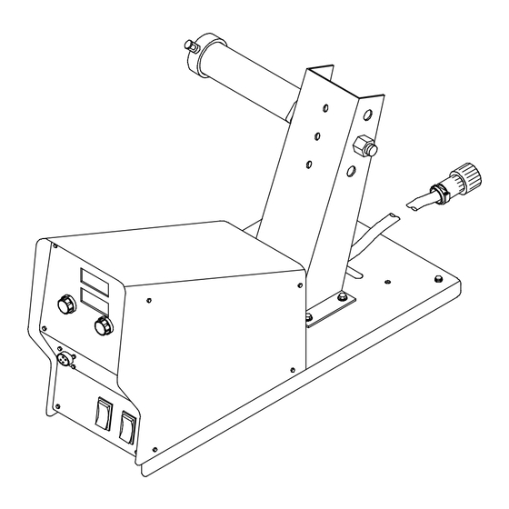
Page 18: Rear Panel Connections And Rotating Drive Assembly
5-4. Rear Panel Connections And Rotating Drive Assembly 14-Pin Control Cable - 10 ft (3.0 m) Shielding Gas Valve Fitting Connect customer-supplied gas hose with 5/8-18 right-hand threads. Shielding gas pressure not to exceed 100 PSI (689 kPa). Rating Label Location Weld Cable Terminal Weld Cable Drive Assembly... -
Page 19: 14-Pin Plug Plg12 Information
5-5. 14-Pin Plug PLG12 Information Pin* Pin Information 24 volts AC with respect to socket G. Contact closure to A completes 24 volts AC contactor control circuit. Circuit common for 24 volts AC circuit. +10 volts DC input from power source to wire feeder with respect to socket D. Remote control circuit common. -
Page 20: Installing And Threading Welding Wire
5-7. Installing And Threading Welding Wire Install wire guides and Install wire spool. Adjust tension nut so anti-wear guide. wire is taut when wire feed stops. Install drive rolls. Pressure Indicator Scale Pressure Adjust Rear Pressure Rolls Adjust Front Rolls No Wire Slip Wire Slips NONCONDUCTIVE... -
Page 21: Setting Internal Dip Switches
5-8. Setting Internal DIP Switches Remove wrapper. DIP Switch S1 On Motor Board PC1 DIP Switch S2 On Motor Board PC1 Setting Current Detect Override (S1-1) Current detect override is used to disable run-in when a welding pow- er source is used that doesn’t pro- vide current feedback through the 14-pin receptacle. -
Page 22: Equipment Dip Switch Settings
5-9. Equipment DIP Switch Settings Remove wrapper. Install wrapper when finished. Digital Meter Functions Standard Standard Motor Motor Inches/Minute Meters/Minute Tools Needed: 1/4 in Ref. 802 946 OM-235 688 Page 18... -
Page 23: Section 6 − Operation
SECTION 6 − OPERATION 6-1. Power Switch Power Switch 802 827-A 6-2. Jog/Purge Jog/Purge Push Button Wire Speed Control Gun Trigger Receptacle Pressing the Jog/Purge switch al- lows the operator to jog wire without energizing the weld power or gas valve circuit. -
Page 24: Trigger Hold Switch
6-3. Trigger Hold Switch 802 828-A • To use the trigger hold function, place the Trigger Hold Switch seconds before releasing it. Welding will trigger hold switch in the On position. continue when the trigger is released. Trigger hold allows the operator to weld with- •... -
Page 25: Synergic Operation Will Only Operate When Connected To Invision 350 Mpa
Arc Length Control pulse MIG arc length. This arc length will be to match the wire speed. The S-74 MPa will allow synergic maintained as you increase or decrease After setting the Wire Type and Gas on the Pulse MIG operation when used with Invision 350 MPa arc length can be ad- wire speed. -
Page 26: Section 7 − Maintenance
SECTION 7 − MAINTENANCE 7-1. Routine Maintenance Maintain more often Disconnect power before maintaining. during severe conditions. 3 Months Clean and Repair or tighten Replace replace weld unreadable cracked terminals. labels. weld cable. Replace Check Check gas Check gun cracked 14-pin cord. -
Page 27: Diagnostics
7-2. Diagnostics Wrapper Motor Control Board PC1 LED3 Front panel is shown removed for purpose of illustration only. In actual use, front panel would be in place. Display On LED3 Sequence On Meter Motor Control Board PC1 Indicated Error (If Equipped) HELP 11 1 Blink Communication Error... -
Page 28: Troubleshooting
7-3. Troubleshooting Disconnect power before troubleshooting. Trouble Remedy Wire feeds, shielding gas flows, but Check cable connections. Check cables for continuity, and repair or replace cables if necessary electrode wire is not energized. (see Section 5-4). Wire feeder is on, display does not light Check and reset circuit breaker at welding power source. -
Page 29: Section 8 − Electrical Diagram
SECTION 8 − ELECTRICAL DIAGRAM 235 643-A Figure 8-1. Circuit Diagram OM-235 688 Page 25... -
Page 30: Section 9 − Parts List
SECTION 9 − PARTS LIST Hardware is common and not available unless listed. Fig. 9-3 Fig. 9-2 805 066-A Figure 9-1. Main Assembly OM-235 688 Page 26... - Page 31 Item Item Part Part Description Description Quantity Quantity Figure 9-1. Main Assembly ....159 647 Insulator, Motor Clamp ......... . .
- Page 32 Hardware is common and not available unless listed. 11 8 805 067-A Figure 9-2. Control Box Item Diagram Part marking Description Quantity Figure 9-2. Control Box (Figure 9-1 Item 21) ....200 555 Wrapper, Feeder .
- Page 33 Item Diagram Part marking Description Quantity Figure 9-2. Control Box (Figure 9-1 Item 21) ....213 134 Knob, Encoder 1.670 Dia X .250 Id Push On W/Spring .
- Page 34 Hardware is common and not available unless listed. See Table 9-1 For Drive Roll & Wire Guide Kits 803 790-A Figure 9-3. Drive Assembly, Wire Item Diagram Part marking Description Quantity Figure 9-3. Drive Assembly, Wire (Figure 9-1 Item 4) .
- Page 35 Item Diagram Part marking Description Quantity Figure 9-3. Drive Assembly, Wire (Continued) ..... 203 631 Pressure Arm, S/L & Vert S/R 4 Roll (Consisting Of) .
- Page 36 Table 9-1. Drive Roll And Wire Guide Kits OM-235 688 Page 32...
- Page 37 Notes SOCKET/WRENCH SELECTION TABLE SOCKET/WRENCH SELECTION TABLE (U.S. STANDARD) (METRIC) Specifications Socket or Wrench Size Specifications Socket or Wrench Size U.S. Bolt Decimal Bolt Bolt Decimal Bolt Diameter Equivalent Diameter Equivalent 1/4 in .250 in 3/8 in 7/16 in 6 mm .2362 in 10 mm 10 mm...
- Page 38 Notes MATERIAL THICKNESS REFERENCE CHART 24 Gauge (.025 in) 22 Gauge (.031 in) 20 Gauge (.037 in) 18 Gauge (.050 in) 16 Gauge (.063 in) 14 Gauge (.078 in) 1/8 in (.125 in) 3/16 in (.188 in) 1/4 in (.25 in) 5/16 in (.313 in) 3/8 in (.375 in) 1/2 in (.5 in)
- Page 39 Effective January 1, 2009 (Equipment with a serial number preface of LK or newer) This limited warranty supersedes all previous Miller warranties and is exclusive with no other Warranty Questions? guarantees or warranties expressed or implied. LIMITED WARRANTY − Subject to the terms and conditions...
- Page 40 Contact the Delivering Carrier to: File a claim for loss or damage during shipment. For assistance in filing or settling claims, contact your distributor and/or equipment manufacturer’s Transportation Department. © ORIGINAL INSTRUCTIONS − PRINTED IN USA 2009 Miller Electric Mfg. Co. 2009−01...
Need help?
Do you have a question about the S-74 MPa and is the answer not in the manual?
Questions and answers