Table of Contents
Troubleshooting

Related Manuals for Miller Gold Seal 160 i


Summary of Contents for Miller Gold Seal 160 i
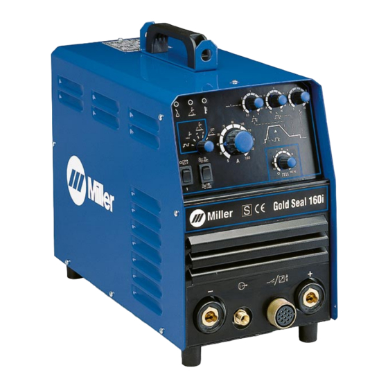
- Page 1 OM-189 116A June 1999 Effective with Serial N 230 Volt – 159 262 240 Volt – 160 261 Processes TIG (GTAW) Welding Stick (SMAW) Welding Description Arc Welding Power Source Gold Seal 160 i Visit our website at www.MillerWelds.com...
- Page 2 1929, he made sure his products offered long-lasting value and superior quality. Like you, his customers couldn’t afford anything less. Miller products had to be more than the best they could be. They had to be the best you could buy.
-
Page 3: Table Of Contents
TABLE OF CONTENTS The following terms are SECTION 1 – SAFETY PRECAUTIONS - READ BEFORE USING ..used interchangeably 1-1. Symbol Usage ..........throughout this manual: TIG = GTAW 1-2. -
Page 4: Declaration Of Conformity
Declaration of Conformity Manufacturer’s Name: ITW WELDING PRODUCTS ITALY S.r.l. Manufacturer’s Address: Via Privata Iseo, 6/E 20098 San Giuliano Milanese, Italy Declares that this product: Gold Seal 160 i Conforms to the following Directives and Standards: Directives Electromagnetic Compatibility Directives: 89/336/EEC Low Voltage: 73/23/EEC Machinery Directives: 89/392/EEC And their amendments 91/368/EEC, 93/31/EEC, 93/44/EEC, 93/68/EEC... -
Page 5: Section 1 - Safety Precautions - Read Before Using
SECTION 1 – SAFETY PRECAUTIONS - READ BEFORE USING som _nd_7/02 1-1. Symbol Usage Means Warning! Watch Out! There are possible hazards with this procedure! The possible hazards are shown in the adjoining symbols. This group of symbols means Warning! Watch Out! possible Y Marks a special safety message. - Page 6 ARC RAYS can burn eyes and skin. BUILDUP OF GAS can injure or kill. D Shut off shielding gas supply when not in use. Arc rays from the welding process produce intense D Always ventilate confined spaces or use visible and invisible (ultraviolet and infrared) rays that can burn eyes and skin.
-
Page 7: Additional Symbols For Installation, Operation, And Maintenance
1-3. Additional Symbols For Installation, Operation, And Maintenance FIRE OR EXPLOSION hazard. MOVING PARTS can cause injury. D Do not install or place unit on, over, or near D Keep away from moving parts such as fans. combustible surfaces. D Keep all doors, panels, covers, and guards D Do not install unit near flammables. -
Page 8: Principal Safety Standards
1-4. Principal Safety Standards Safety in Welding, Cutting, and Allied Processes, ANSI Standard Z49.1, Boulevard, Rexdale, Ontario, Canada (phone: from American Welding Society, 550 N.W. LeJeune Rd, Miami FL 33126 800–463–6727 or in Toronto 416–747–4044, website: www.csa–in- (phone: 305-443-9353, website: www.aws.org). ternational.org). -
Page 9: Section 2 - Installation
SECTION 2 – INSTALLATION 2-1. Specifications Amperes Input at Maximum Rated Load Output, Rated Welding Output IP Rating Weight Open-Circuit Range DC 50/60 Hz, Single-Phase Voltage DC Voltage DC 230 V 240 V 160 A @ 16.4 Volts DC, 33 lb 5 –... -
Page 10: Volt-Ampere Curve
2-3. Volt-Ampere Curve Volt-ampere curve shows mini- mum and maximum voltage and amperage output capabilities of unit. 802 276 2-4. Selecting A Location Rating Label Use rating label to determine input power needs. Line Disconnect Device Locate unit near correct input pow- er supply. -
Page 11: Typical Connections
2-5. Typical Connections A. Typical Stick (SMAW) Connections B. Typical TIG (GTAW) Connections 2-6. Front Panel Connections Gas Hose Connector Remote Contactor And Current Control Receptacle OM-189 116 Page 7... -
Page 12: Weld Output Terminals And Selecting Cable Sizes
2-7. Weld Output Terminals And Selecting Cable Sizes Total Cable (Copper) Length In Weld Circuit Not Exceeding 150 ft 200 ft 250 ft 300 ft 350 ft 400 ft 100 ft (30 m) Or Less (45 m) (60 m) (70 m) (90 m) (105 m) (120 m) -
Page 13: Connecting Input Power
2-9. Connecting Input Power Rating Label Supply correct input power. See Section 2-8. Line Disconnect Device Check input voltage available at site. Y Always connect grounding conductor first. = GND/PE OM-189 116 Page 9... -
Page 14: Section 3 - Operation
SECTION 3 – OPERATION 3-1. Controls Machine On Indicator Light Welding On Indicator Light Thermal Cutout Warning Indicator Light Welding Current Control Down Slope And Up Slope Time Control Base Current Control Post-Gas time Control Pulse Frequency Control HF Or Lift-Arc Selector 10 Control Panel Or Remote Control Selector 11 Function selector... -
Page 15: Troubleshooting
4-2. Troubleshooting Trouble Remedy No weld output; unit completely inop- Be sure Power switch is On (see Section 3-1). erative. Be sure line disconnect switch is On (see Section 2-9). Check line fuse(s) and replace if necessary (see Sections 2-9). Check for proper input power connections (see Sections 2-8 and/or 2-9). -
Page 16: Section 5 - Electrical Diagrams
SECTION 5 – ELECTRICAL DIAGRAMS S-142 310 Figure 5-1. Circuit Diagram For 230 Volt Input Models OM-189 116 Page 12... - Page 17 S-142 311 Figure 5-2. Circuit Diagram For 240 Volt Input Models OM-189 116 Page 13...
-
Page 18: Section 6 - Selecting And Preparing Tungsten Electrode
SECTION 6 – SELECTING AND PREPARING TUNGSTEN ELECTRODE gtaw2 7/97 NOTE For additional information, see your distributor for a handbook on the Gas Tungsten Arc Welding (GTAW) process. Wear clean gloves to prevent contamination of tungsten electrode. 6-1. Selecting Tungsten Electrode Amperage Range - Gas Type - Polarity Electrode Diameter... -
Page 19: Preparing Tungsten For Dc Electrode Negative (Dcen) Welding
6-3. Preparing Tungsten For DC Electrode Negative (DCEN) Welding Tungsten Electrode Tapered End Grind end of tungsten on fine grit, hard abrasive wheel before weld- ing. Do not use wheel for other jobs or tungsten can become contami- nated causing lower weld quality. 2-1/2 Times Electrode Diameter Stable Arc... -
Page 20: Section 7 - Guidelines For Tig Welding (Gtaw)
SECTION 7 – GUIDELINES FOR TIG WELDING (GTAW) 7-1. Positioning the Torch Y Grinding the tungsten elec- trode produces dust and fly- ing sparks which can cause injury and start fires. Use lo- cal exhaust (forced ventila- tion) at the grinder or wear an approved respirator. -
Page 21: Torch Movement During Welding
7-2. Torch Movement During Welding Tungsten Without Filler Rod Welding direction Form pool Tilt torch Move torch to front of pool. Repeat process. Tungsten With Filler Rod Welding direction Form pool Tilt torch Add filler metal Remove rod Move torch to front of pool. -
Page 22: Positioning Torch Tungsten For Various Weld Joints
7-3. Positioning Torch Tungsten For Various Weld Joints Butt Weld And Stringer Bead “T” Joint Lap Joint Corner Joint ST-162 003 / S-0792 OM-189 116 Page 18... - Page 23 Notes OM-189 116 Page 19...
-
Page 24: Section 8 - Parts List
SECTION 8 – PARTS LIST Hardware is common and not available unless listed. Figure 8-1. Main Assembly OM-189 116 Page 20... - Page 25 Table 8-1. Parts List Item Code Diagram Ref. 156002025 UR.0.0.13 156011021 VG.0.0.11 156121007 VG.0.0.12 057084088 VG.0.10 Logic P.C.B.6 057084074 VG.0.4 Controls P.C.B.5 356029201 VG.0.0.13 056067213 VG.0.0.27 S2-S3 056020046 VG.0.0.14 056020047 VG.0.0.15 156118021 VG.0.0.16 057098003 UR.1.4 756005018 VG.0.0.17 956142309 VG.0.0.18 056076209 VG.0.0.19 556049361 VG.0.0.20...
- Page 26 Notes...
- Page 27 Effective January 1, 2002 This limited warranty supersedes all previous Miller warranties and is exclusive with no other guarantees or warranties expressed or implied. LIMITED WARRANTY – Subject to the terms and conditions Remote Controls below, Miller Europe S.r.l., Milan Italy, warrants to its original...
- Page 28 FAX: 44 (0) 1204-598066 Miller Electric Mfg. Co. An Illinois Tool Works Company 1635 West Spencer Street Appleton, WI 54914 USA International Headquarters–USA Phone: 920-735-4505 USA & Canada FAX: 920-735-4134 International FAX: 920-735-4125 PRINTED IN USA 2003 Miller Electric Mfg. Co. 1/03...
Need help?
Do you have a question about the Gold Seal 160 i and is the answer not in the manual?
Questions and answers