Miller S-74 MPa Plus Control Box Cobot CE Owner's Manual
Hide thumbs
Also See for S-74 MPa Plus Control Box Cobot CE:
- Owner's manual (52 pages) ,
- Technical manual (56 pages) ,
- Owner's manual (56 pages)
Table of Contents
Advertisement
Quick Links
Advertisement
Table of Contents
Troubleshooting

Related Manuals for Miller S-74 MPa Plus Control Box Cobot CE


Summary of Contents for Miller S-74 MPa Plus Control Box Cobot CE
- Page 1 OM-289404B 2022-08 Processes MIG (GMAW) Welding Pulsed MIG (GMAW-P) Welding Flux Cored (FCAW) Welding Description Wire Feeder S-74 MPa Plus Control Box Cobot CE OWNER’S MANUAL For product information, Owner’s Manual translations, and more, visit www.MillerWelds.com...
- Page 2 We know you don’t have time to do it any other way. That’s why when Niels Miller first started building arc welders in 1929, he made sure his products offered long-lasting value and superior quality.
-
Page 3: Table Of Contents
TABLE OF CONTENTS SECTION 1 – SAFETY PRECAUTIONS – READ BEFORE USING..............1 Symbol Usage . - Page 5 DECLARATION OF CONFORMITY for European Community (CE marked) products. MILLER Electric Mfg. LLC, 1635 Spencer Street, Appleton, WI 54914 U.S.A. declares that the product(s) identified in this declaration conform to the essential requirements and provisions of the stated Council Directive(s), Commission Regulation(s) and Standard(s).
- Page 6 DECLARATION OF CONFORMITY For United Kingdom (UKCA marked) products. MILLER Electric Mfg. LLC, 1635 West Spencer Street, Appleton, WI 54914 U.S.A. declares that the product(s) identified in this declaration conform to the essential requirements and provisions of the stated Regulation(s) and Standard(s).
-
Page 7: Section 1 - Safety Precautions - Read Before Using
SECTION 1 – SAFETY PRECAUTIONS – READ BEFORE USING Protect yourself and others from injury—read, follow, and save these important safety precautions and operating instructions. 1-1. Symbol Usage DANGER! – Indicates a hazardous situation which, if not avoided, will result in death or serious injury. The possible hazards are shown in the adjoining symbols or explained in the text. - Page 8 HOT PARTS can burn. WELDING can cause fire or explosion. � Do not touch hot parts bare handed. � Allow cooling period before working on equipment. Welding on closed containers, such as tanks, drums, or pipes, can cause them to blow up. �...
-
Page 9: Additional Hazards For Installation, Operation, And Maintenance
� Never weld on a pressurized cylinder—explosion will result. CYLINDERS can explode if � Use only correct compressed gas cylinders, regulators, hoses, damaged. and fittings designed for the specific application; maintain them Compressed gas cylinders contain gas under high and associated parts in good condition. pressure. -
Page 10: California Proposition 65 Warnings
� To reduce possible interference, keep weld cables as short as ARC WELDING can cause possible, close together, and down low, such as on the floor. interference. � Locate welding operation 100 meters from any sensitive electronic equipment. � Electromagnetic energy can interfere with sensitive electronic equipment such as microprocessors, �... -
Page 11: Section 2 - Consignes De Sécurité - Lire Avant Utilisation
SECTION 2 – CONSIGNES DE SÉCURITÉ - LIRE AVANT UTILISATION Pour écarter les risques de blessure pour vous-même et pour autrui — lire, appliquer et ranger en lieu sûr ces consignes relatives aux précautions de sécurité et au mode opératoire. 2-1. - Page 12 � S’assurer que tous les panneaux et couvercles sont correctement LES ACCUMULATIONS DE GAZ en place. risquent de provoquer des blessures � Fixer le câble de retour de façon à obtenir un bon contact métal- ou même la mort. métal avec la pièce à souder ou la table de travail, le plus près possible de la soudure.
-
Page 13: Symboles De Dangers Supplémentaires En Relation Avec L'installation, Le Fonctionnement Et La Maintenance
� Brancher le câble de masse sur la pièce le plus près possible de � Les porteurs d’implants médicaux doivent consulter leur médecin la zone de soudage pour éviter le transport du courant sur une lon- et le fabricant du dispositif avant de s’approcher de la zone où se gue distance par des chemins inconnus éventuels en provoquant déroule du soudage à... -
Page 14: Proposition Californienne 65 Avertissements
� Affûter l'électrode au tungstène uniquement à la meuleuse dotée LIRE LES INSTRUCTIONS. de protecteurs. Cette manœuvre est à exécuter dans un endroit sûr lorsque l'on porte l'équipement homologué de protection du vi- � Lire et appliquer les instructions sur les étiquettes sage, des mains et du corps. -
Page 15: Informations Relatives Aux Cem
Safety in Welding, Cutting, and Allied Processes, CSA Standard Subpart N, Part 1910 Subpart Q, and Part 1926, Subpart J. Website: W117.2 from Canadian Standards Association. Website: www. csa- www.osha.gov. group.org. OSHA Important Note Regarding the ACGIH TLV, Policy Statement on the Uses of TLVs and BEIs. -
Page 16: Section 3 - Definitions
Some symbols are found only on CE products. Some symbols are found only on CE products. 1-1. Additional Safety Symbols And Definitions 1-1. Additional Safety Symbols And Definitions 1-1. Additional Safety Symbols And Definitions SECTION 3 – DEFINITIONS Some symbols are found only on CE products. Warning! Watch Out! There are possible hazards as shown by the symbols. - Page 17 machine or welding. Keep flammables away from welding. Do not weld near flammables. Welding sparks can cause fires. Have a fire extinguisher nearby, and have a watchperson ready to use it. Do not cut on drums or any closed containers. Safe62 201 Safe40 2012 05 Safe14 2012...
-
Page 18: Miscellaneous Symbols And Definitions
Misc Symbols 2016 08 Engine Driven Contractor On Engine Driven Contractor On Crater/Burnback Crater/Burnback 3 Phase 3 Phase Output Output On Output Alternator with Output On Alternator with 3-2. Miscellaneous Symbols And Definitions ions document. Make sure section heading components are Rectifier Rectifier Adjust... -
Page 19: Section 4 - Specifications
Information About Default Weld Parameters And Settings NOTICE – Each welding application is unique. Although certain Miller Electric products are designed to determine and default to certain typical welding parameters and settings based upon specific and relatively limited application variables input by the end user, such default settings are for reference purposes only;... -
Page 20: Section 5 - Installation
SECTION 5 – INSTALLATION 5-1. Equipment Connection Diagram The integrator shall conduct a risk assessment for the collaborative operation as described in ISO 10218-2:2011: Robots and robotic devices — Safety requirements for industrial robots — Part 2: Robot systems and integration. �... -
Page 21: Installing Control Box And Adjusting Tilt
5-2. Installing Control Box And Adjusting Tilt 4-2. Installing Control Box And Adjusting Tilt 1 Weld Control 2 Bracket 3 Screw Bracket and screws are installed onto bottom of control at factory. 4-2. Installing Control Box And Adjusting Tilt 4 Swivel Loosen screws. -
Page 22: 14-Pin Plug Information For Connecting Wire Feeder To Power Source
5-4. 14–Pin Plug Information For Connecting Wire Feeder To Power Source Remote 14 Pin* Pin Information 4-4. 14-Pin Plug Information For Connecting Wire Feeder To Power Source 24 volts AC with respect to socket G. Contact closure to A completes 24 volts AC contactor control circuit. Circuit common for 24 volts AC circuit. -
Page 23: Section 6 - Operation
SECTION 5 OPERATION SECTION 5 OPERATION SECTION 6 – OPERATION 5-1. Power Switch Power Switch Power Switch 6-1. Power Switch 1 Power Switch Ref. 255193-D Ref. 255193-D 5-2. Jog/Purge Switch witch 6-2. Jog/Purge Switch Jog/Purge Switch Jog/Purge Switch Ref. 255193-D Ref. -
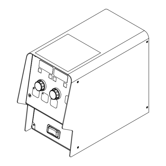
Page 24: Front Panel Controls
6-3. Front Panel Controls 5-3. Front Panel Controls Ref. 271487-A 1 Left Display (See Section 6-4) 4 Adjust Control Right (See Section 6-6) 6 Setup Push Button (See Section 6-7) 2 Right Display (See Section 6-5) 7 Start Push Button (See Section 6-8) 5 Program Select Push Button (See Sec- tion 6-10) 3 Adjust Control Left (See Section 6-6) -
Page 25: Left Display
5-4. Left Display 5-4. Left Display 6-4. Left Display Left Display 1 Left Display � See Section 8-2for selection of arc length and voltage display. The left display shows voltage or arc length. 2 Arc Length LED The unit displays both preset and actual arc 3 Volts LED voltage. -
Page 26: Adjust Control Left/Right
6-6. Adjust Control Left/Right 5-6. Adjust Control Left/Right 1 Adjust Control Use Adjust control to change various param- eters or menu items. Use left control to adjust volts or arc length. Use right control to adjust amperage or wire feed speed. 6-7. -
Page 27: 6-10. Program Select Push Button
6-10. Program Select Push Button am Select Push Button 1 Program Select Push Button 2 Program Indicating LEDs Program select is for setup adjustments and initial weld. Active function (TPS or Dual Schedule) will override previous functions. OM-289404 Page 21... -
Page 28: 6-11. Power Source Selection Menu
5-11. Power Source Selection Menu 6-11. Power Source Selection Menu 1 Left Display 2 Right Display � When the feeder is turned on, the Power Source Selection Menu allows the operator to select a default power source. Selecting a default power source, automatically sets the correct Vmin and Vmax settings for adjusting the output voltage of the power source. -
Page 29: 6-12. Operational Terms
6-12. Operational Terms The following is a list of terms and their definitions as they apply to this wire feeder: General Terms: Cold Wire Jog Feeding wire without contactor or gas valve being energized. Sequence A portion of the weld program, such as preflow, run-in, start, weld, crater, burnback, and postflow. Weld Program A group of sequences that make up a weld cycle. -
Page 30: Section 7 - Setting Sequence Parameters
SECTION 6 SETTING SEQUENCE PARAMETERS 6-1. Sequence Parameters In A Program SECTION 7 – SETTING SEQUENCE PARAMETERS 7-1. Sequence Parameters In A Program Sequence Parameters Volts Seconds Inches 0–5.0 1 Preflow x0.1–x1.00 2 Run-In 0.1–0.5 3 Start 0–100.0 4 Weld 0.00–5.00 5 Crater 0.0–10.0... -
Page 31: Section 8 - Programming
SECTION 8 – PROGRAMMING 8-1. Setup Menu To enter the SETUP MENU press and re- released during welding the unit goes into pressed and before the welding arc will be lease the SETUP button. The SETUP trigger hold - pressing and holding trigger allowed to be active. -
Page 32: Setup Menu Level 2
8-2. Setup Menu Level 2 limit setting will change if the wire and gas parameters cannot be adjusted when Pa- To enter the SETUP MENU LEVEL 2 press program selection is changed. rameter Lock is set to (ON). and hold the SETUP button. The SETUP MENU INDICATOR and the SETUP BUT- Voltage Range Limit (MAX) - Indicated in Retract (RTRK) - Enables the retract func-... -
Page 33: Setting A Start Sequence In Synergic Pulse
8-3. Setting A Start Sequence In Synergic Pulse Items that can be adjusted in this menu are: To turn on a Start sequence, press the � When the PULS option in the SETUP START button. The START ON INDICATOR MENU LEVEL 2 is set to VOLT, the Start Mode (STRT) - Sets the Start Mode to will illuminate indicating Start is active. -
Page 34: Setting A Start Sequence In Non-Synergic Pulse Or Mig
8-4. Setting A Start Sequence In Non-Synergic Pulse Or MIG To exit the START MENU, press and re- Start Voltage (VOLT) - Sets the voltage dur- To turn on a Start sequence, press the lease the START button. ing the Start Time. Range of this setting is START button. -
Page 35: Setting A Crater Fill Sequence In Synergic Pulse
8-5. Setting A Crater Fill Sequence In Synergic Pulse To turn on Crater Fill, press the CRATER Crater Mode (CRTR) - Sets the Crater Crater Voltage (VOLT) - Sets the voltage button. The CRATER ON INDICATOR will il- mode to (AUTO or MAN). When the Crater during the Crater Fill time. -
Page 36: Setting A Crater Fill Sequence In Non-Synergic Pulse Or Mig
8-6. Setting A Crater Fill Sequence In Non-Synergic Pulse Or MIG To exit the CRATER MENU press and re- setting is dependent on the power source or To turn on Crater Fill, press the CRATER lease the CRATER button. voltage range of selected power source. button. -
Page 37: Profile Pulse
8-7. Profile Pulse Figure 1: Constant travel speed with P.FRQ set to 0.1 Figure 2: Constant travel speed with P.FRQ set to 5.0 Profile Pulse optimizes Aluminum weld bead Profile Pulse Items that can be adjusted in setting is (X0.00 to X0.30). Example: If the appearance by producing welds with consis- the Setup Menu are: wire feed speed is 200 and (P.WFS) is set to... -
Page 38: Section 9 - Maintenance And Troubleshooting
SECTION 9 – MAINTENANCE AND TROUBLESHOOTING SECTION 7 MAINTENANCE & TROUBLESHOOTING 9-1. Routine Maintenance 7-1. Routine Maintenance Disconnect power before maintaining. Disconnect power before maintaining. � = Check ◇ = Change � = Clean � = Replace = Check = Clean = Replace Every Complete Parts List is available at www.MillerWelds.com... -
Page 39: Diagnostics
9-2. Diagnostics The following error messages are shown on the displays to indicate specific errors. Explanations are in the text below. Left Display Right Display Description TRIG Indicates a trigger error. A trigger error occurs if the user has the trigger held for more than two mi- nutes without striking an arc. -
Page 40: Troubleshooting
9-3. Troubleshooting Disconnect power before troubleshooting. Trouble Remedy Pressing gun trigger does not ener- Secure plug from gun control cable into Gun Control receptacle. gize feeder. Shielding gas does not Have nearest Factory Authorized Service Agent check optional water flow switch, if applicable. flow and wire feeder does not feed. - Page 41 OM-289404 Page 35...
-
Page 42: Section 10 - Electrical Diagram
SECTION 10 – ELECTRICAL DIAGRAM Figure 10-1. Circuit Diagram OM-289404 Page 36... - Page 43 251668-B OM-289404 Page 37...
-
Page 44: Section 11 - Parts List
SECTION 6 PARTS LIST SECTION 11 – PARTS LIST 255197-D Figure 11-1. S-74 MPa Plus Remote Control Box Figure 11-1. S-74 MPa Plus Remote Control Box Item Dia. Part Mkgs. Description Figure 11-1. S-74 MPa Plus Remote Control Box .. - Page 45 Figure 11-1. S-74 MPa Plus Remote Control Box Item No. Dia. Mkgs. Part No. Description Quantity +235210 Wrapper, Feeder 274964 Label, Warning General Precautionary (EN/FR/SP) 248313 Circuit Card Assy, Push-Pull Interface RC114 247638 Plug Assy, Remote Control Box 244200 Circuit Card Assy,14 Pin Filter 244581 Cable, Power S-74 MPa Plus (Includes) 139041...
- Page 46 Notes...
- Page 47 Effective January 1, 2022 (Equipment with a serial number preface of NC or newer) This limited warranty supersedes all previous Miller warranties and is exclusive with no other guarantees or war- ranties expressed or implied. � Field Options (NOTE: Field options are cov-...
- Page 48 Appleton, WI 54914 USA tact your distributor and/or equipment manu- facturer’s Transportation Department. International Headquarters–USA USA Phone: 920-735-4505 USA & Canada FAX: 920-735-4134 International FAX: 920-735-4125 For International Locations Visit www.MillerWelds.com ORIGINAL INSTRUCTIONS – PRINTED IN USA © Miller Electric Mfg. LLC 2022-08...
Need help?
Do you have a question about the S-74 MPa Plus Control Box Cobot CE and is the answer not in the manual?
Questions and answers