Advertisement
Quick Links
Description
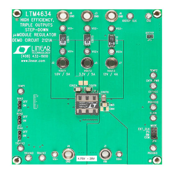
Demonstration circuit 2121A features the
high efficiency, triple 5A/5A/4A step-down power µModule
regulator. The input voltage range is from 4.75V to 28V.
The output voltage range is 0.8V to 5.5V for Channel 1
and Channel 2, 0.8V to 13.5V for Channel 3. Derating is
necessary for certain V
IN
conditions. The DC2121A offers access to the TK/SS pins
allowing the user to program output tracking or soft-start
period. The board operates in continuous conduction mode
in heavy load conditions. For high efficiency at low load
currents, the MODE jumper (JP4) selects pulse-skipping
BoarD photo
Step-Down DC/DC µModule Regulator
LTM
4634, a
®
, V
, frequency and thermal
OUT
DEMO MANUAL DC2121A
Triple Output 5A/5A/4A
mode for noise sensitive applications or Burst Mode
operation in less noise sensitive applications. Channel 1
and 2 can be connected in parallel for a single 10A output
solution with optional jumper resistors. The LTM4634 data
sheet must be read in conjunction with this demo manual
prior to working on or modifying demo circuit DC2121A.
Design files for this circuit board are available at
http://www.linear.com/demo/DC2121A
L, LT, LTC, LTM, Burst Mode, Linear Technology and the Linear logo are registered trademarks of
Linear Technology Corporation. All other trademarks are the property of their respective owners.
LTM4634
®
dc2121af
1
Advertisement

Subscribe to Our Youtube Channel
Related Manuals for Linear Technology DC2121A


Summary of Contents for Linear Technology DC2121A
- Page 1 The board operates in continuous conduction mode L, LT, LTC, LTM, Burst Mode, Linear Technology and the Linear logo are registered trademarks of in heavy load conditions. For high efficiency at low load Linear Technology Corporation. All other trademarks are the property of their respective owners.
- Page 2 OUT3 STEP Quick start proceDure Demonstration circuit DC2121A is an easy way to evaluate adjustable pulse signal between IOSTEP_CLK and GND the performance of the LTM4634. Please refer to Figure test points. The pulse amplitude sets the load step cur- 1 for proper measurement equipment setup and follow rent amplitude.
- Page 3 DEMO MANUAL DC2121A Quick start proceDure – – – LOAD LOAD LOAD – – – – – – – – – Figure 1. Measurement Setup of DC2121A dc2121af...
- Page 4 DEMO MANUAL DC2121A Quick start proceDure Efficiency of Ch1 (V = 1V, FCC Mode) OUT1 100% = 5V = 8V = 12V = 18V = 24V LOAD CURRENT (A) Figure 2. Measured Efficiency on Channel 1 = 1.0V, f = 500kHz, CCM, Channel 2, 3 Disabled...
- Page 5 DEMO MANUAL DC2121A Quick start proceDure Efficiency of Ch3 (V = 12V, FCC Mode) OUT3 100% = 18V = 24V = 28V LOAD CURRENT (A) Figure 4. Measured Efficiency on Channel 3 = 12.0V, f = 500kHz, CCM, Channel 1, 2 Disabled...
- Page 6 DEMO MANUAL DC2121A Quick start proceDure : 50mV/DIV : 2A/DIV OUT_STEP Figure 6. Measured Channel 2 Load Transient = 12V, V = 3.3V, I = 0A to 2.5A OUT1 STEP Slew Rate = 1A/µs STEP : 200mV/DIV : 1A/DIV OUT_STEP Figure 7.
- Page 7 DEMO MANUAL DC2121A Quick start proceDure Figure 8. Thermal Image of LTM4634 = 24V, V = 1.0V, I = 5A, V = 3.3V, I = 5A, V = 12.0V, I = 2A OUT1 LOAD1 OUT2 LOAD2 OUT3 LOAD3 Ambient Temperature = 23.2°C, No Forced Air Flow Figure 9.
- Page 8 DEMO MANUAL DC2121A parts List ITEM REFERENCE PART DESCRIPTION MANUFACTURER/PART NUMBER Required Circuit Components CIN1 Cap., 120µF, 35V, Aluminum Electr., PANASONIC, 35SVPF120M CIN2, CIN3, CIN5 Cap., X5R, 22µF, 35V, 20%,1206 TDK, C3216X5R1V226M160AC COUT1, COUT5 Cap., 470µF, 4V, POSCAP, F8 PANASONIC, 4TPE470MCL COUT4, COUT6 Cap., X5R, 100µF, 6.3V, 20% 1210...
- Page 9 DEMO MANUAL DC2121A parts List ITEM REFERENCE PART DESCRIPTION MANUFACTURER/PART NUMBER Hardware: For Demo Board Only E1-E20 TESTPOINT, TURRET, .094" pbf MILL-MAX, 2501-2-00-80-00-00-07-0 JP1, JP2, JP3 HEADER 3 PIN 0.079 SINGLE ROW SULLIN, NRPN031PAEN-RC HEADER 8 PIN 0.079 DOUBLE ROW SULLIN, NRPN042PAEN-RC HEADER 2 PIN 0.079 SINGLE ROW...
- Page 10 DEMO MANUAL DC2121A schematic Diagram dc2121af...
- Page 11 Information furnished by Linear Technology Corporation is believed to be accurate and reliable. However, no responsibility is assumed for its use. Linear Technology Corporation makes no representa- tion that the interconnection of its circuits as described herein will not infringe on existing patent rights.
- Page 12 Linear Technology Corporation (LTC) provides the enclosed product(s) under the following AS IS conditions: This demonstration board (DEMO BOARD) kit being sold or provided by Linear Technology is intended for use for ENGINEERING DEVELOPMENT OR EVALUATION PURPOSES ONLY and is not provided by LTC for commercial use. As such, the DEMO BOARD herein may not be complete in terms of required design-, marketing-, and/or manufacturing-related protective considerations, including but not limited to product safety measures typically found in finished commercial goods.
- Page 13 X-ON Electronics Largest Supplier of Electrical and Electronic Components Click to view similar products for category: Power Management IC Development Tools Click to view products by manufacturer: Analog Devices Other Similar products are found below : EVAL-ADM1168LQEBZ EVB-EP5348UI MIC23451-AAAYFL EV MIC5281YMME EV DA9063-EVAL ADP122-3.3-EVALZ ADP130- 0.8-EVALZ ADP130-1.2-EVALZ ADP130-1.5-EVALZ ADP130-1.8-EVALZ ADP1714-3.3-EVALZ ADP1716-2.5-EVALZ ADP1740-1.5- EVALZ ADP1752-1.5-EVALZ ADP1828LC-EVALZ ADP1870-0.3-EVALZ ADP1871-0.6-EVALZ ADP1873-0.6-EVALZ ADP1874-0.3- EVALZ ADP1882-1.0-EVALZ ADP199CB-EVALZ ADP2102-1.25-EVALZ ADP2102-1.875EVALZ ADP2102-1.8-EVALZ ADP2102-2-...
Need help?
Do you have a question about the DC2121A and is the answer not in the manual?
Questions and answers