Advertisement
Quick Links
Description
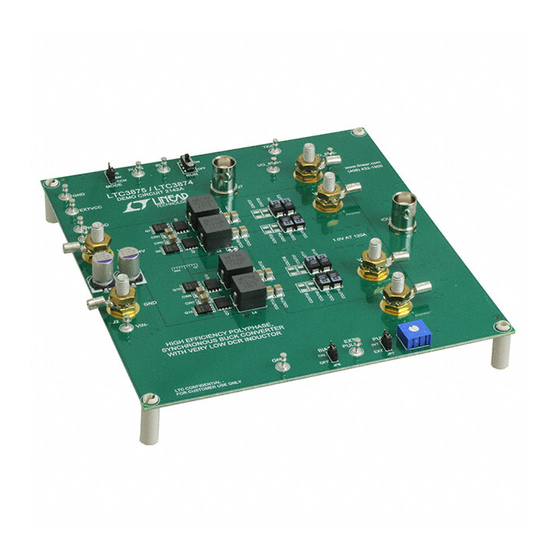
Demonstration circuit 2142A is a high efficiency, high
density, 4-phase synchronous buck converter with a 4.5V
to 14V input range. It can supply 120A maximum load
current at a 1.0V output. This demo board incorporates
the LTC3875EUJ and LTC3874IUFD controllers.
The
LTC
3875
is a feature-rich dual phase synchronous
®
buck controller with very low DCR current sensing capa-
bility, on-chip drivers and remote output voltage sens-
ing. The LTC3874 is a compact dual phase synchronous
buck phase extender with very low DCR current sensing
capability, on-chip drivers and immediate response to
master IC's fault.
This board is setup with 0.32mΩ DCR inductor. The tem-
perature compensation function guarantees accurate cur-
rent limit over a wide temperature range with DCR sensing.
The DC2142 can provide high efficiency, high power density
and compact solutions for telecom and datacom systems,
performance summary
PARAMETER
Input Voltage Range
Output Voltage, V
OUT
Maximum Output Current, I
Typical Efficiency, V
OUT
Typical Switching Frequency
Arrow.com.
Downloaded from
High Efficiency, Single-Output Synchronous
Buck Converter with Very Low DCR Inductor
CONDITIONS
V
= 4.5V to 14V, I
IN
V
= 4.5V to 14V, V
OUT
IN
V
= 12V, V
IN
DEMO MANUAL DC2142A
LTC3875EUJ & LTC3874IUFD
industrial and medical instruments, DC power distribution
systems and computer systems. The LTC3875 is available
in a 40-pin 6mm × 6mm QFN package. The LTC3874 is
available in a 28-lead (4mm × 5mm) QFN Package.
To shut down the converter, set the RUN pin voltage be-
low 1.4V (SW1: OFF). Use the JP1 jumper to select burst
mode, pulse skipping mode or forced continuous mode
operation at light load. Switching frequency is preset at
about 400kHz, and it can be easily modified from 250kHz
to 770kHz. An on-board dynamic circuit is also available
for transient test. The LTC3875 and LTC3874 data sheets
give a complete description of these parts, and must be
read in conjunction with this DC2142A quick start guide
Design files for this circuit board are available at
http://www.linear.com/demo/DC2142A
L, LT, LTC, LTM, Linear Technology and the Linear logo are registered trademarks of Linear
Technology Corporation. All other trademarks are the property of their respective owners.
Specifications are at T
= 25°C
A
= 0A to 120A
OUT1
= 1.0V
OUT1
= 1.0 V, I
= 120A
OUT1
OUT1
VALUE
4.5V to 14V
1.0V ±2%
120A
87.4%
400kHz
dc2142af
1
Advertisement

Related Manuals for Linear Technology DC2142A


Summary of Contents for Linear Technology DC2142A
- Page 1 The DC2142 can provide high efficiency, high power density L, LT, LTC, LTM, Linear Technology and the Linear logo are registered trademarks of Linear and compact solutions for telecom and datacom systems, Technology Corporation. All other trademarks are the property of their respective owners.
- Page 2 DEMO MANUAL DC2142A Quick start proceDure Demonstration circuit 2142A is easy to set up to evaluate 5. Once the proper output voltages are established, ad- the performance of the LTC3875EUJ and LTC3874IUFD. just the loads within the operating range and observe...
- Page 3 DEMO MANUAL DC2142A Quick start proceDure – – – – – LOAD (0A ~ 120A) 4.5V TO 14V – dc2142a F01 Figure 1. Proper Measurement Equipment Setup – Figure 2. Measuring Output Voltage Ripple dc2142af Arrow.com. Arrow.com. Arrow.com. Downloaded from...
- Page 4 DEMO MANUAL DC2142A Quick start proceDure Efficiency vs Load Current, V = 1.0V LOAD CURRENT (A) dc2142a F03 Figure 3. Efficiency vs Load Current at V = 12V, V = 1.0V, f = 400kHz Figure 4. Thermal Performance at V = 12V, V = 1.0V, I...
- Page 5 DEMO MANUAL DC2142A Quick start proceDure Current Sharing vs Load Current, V = 1.0V CHANNEL 1 CHANNEL 2 CHANNEL 3 ±3.6% CHANNEL 4 LOAD CURRENT (A) dc2142a F05 Figure 5. Current Sharing vs Load Current at V = 12V, V = 1.0V, f...
-
Page 6: Parts List
DEMO MANUAL DC2142A Quick start proceDure (20MHz BW) [20mV/DIV] 30A TO 60A LOAD STEP Figure 7. Transient Performance at V = 12V, V = 1.0V, I = 30A ~ 60A parts List ITEM REFERENCE PART DESCRIPTION MANUFACTURER/PART NUMBER Required Circuit Components CIN1, CIN2, CIN3, CIN4, CIN5, CIN6, CAP, 1210, 10µF, 20%, 35V X5R... - Page 7 DEMO MANUAL DC2142A parts List ITEM REFERENCE PART DESCRIPTION MANUFACTURER/PART NUMBER Q1, Q5, Q10, Q15 XSTR, POWER MOSFET INFINEON BSC050NE2LS Q3, Q7, Q13, Q17 XSTR, POWER MOSFET INFINEON BSC010NE2LSI XSTR, N-CHANNEL DMOS FET FAIRCHILD 2N7002A Q20, Q21 XSTR, MOSFET, N-CHANNEL 30V VISHAY SUD50N04-8M8P-4GE3 RES, 0603, 20kΩ, 5%, 1/10W...
- Page 8 DEMO MANUAL DC2142A parts List ITEM REFERENCE PART DESCRIPTION MANUFACTURER/PART NUMBER Q2, Q4, Q6, Q8, Q11, Q14, Q16, Q18 XSTR, POWER MOSFET OPTION OPTION R88, R92 RES, 0603, 20kΩ, 5% 1/10W VISHAY CRCW060320K0JNEA R68, R87 RES, 0603, 0Ω, JUMPER VISHAY CRCW06030000Z0EA...
-
Page 9: Schematic Diagram
DEMO MANUAL DC2142A schematic Diagram dc2142af Arrow.com. Arrow.com. Arrow.com. Arrow.com. Arrow.com. Arrow.com. Arrow.com. Arrow.com. Arrow.com. Downloaded from Downloaded from Downloaded from Downloaded from Downloaded from Downloaded from Downloaded from Downloaded from Downloaded from... - Page 10 DEMO MANUAL DC2142A schematic Diagram dc2142af Arrow.com. Arrow.com. Arrow.com. Arrow.com. Arrow.com. Arrow.com. Arrow.com. Arrow.com. Arrow.com. Arrow.com. Downloaded from Downloaded from Downloaded from Downloaded from Downloaded from Downloaded from Downloaded from Downloaded from Downloaded from Downloaded from...
- Page 11 Information furnished by Linear Technology Corporation is believed to be accurate and reliable. However, no responsibility is assumed for its use. Linear Technology Corporation makes no representa- tion that the interconnection of its circuits as described herein will not infringe on existing patent rights.
- Page 12 Linear Technology Corporation (LTC) provides the enclosed product(s) under the following AS IS conditions: This demonstration board (DEMO BOARD) kit being sold or provided by Linear Technology is intended for use for ENGINEERING DEVELOPMENT OR EVALUATION PURPOSES ONLY and is not provided by LTC for commercial use. As such, the DEMO BOARD herein may not be complete in terms of required design-, marketing-, and/or manufacturing-related protective considerations, including but not limited to product safety measures typically found in finished commercial goods.
Need help?
Do you have a question about the DC2142A and is the answer not in the manual?
Questions and answers