
Related Manuals for Lincoln Electric CITOTIG 200 AC/DC


Summary of Contents for Lincoln Electric CITOTIG 200 AC/DC
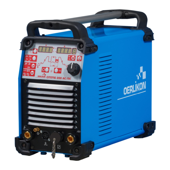
- Page 1 IM3107 10/2022 REV05 CITOTIG 200 AC/DC OPERATOR’S MANUAL ENGLISH Lincoln Electric Bester Sp. z o.o. ul. Jana III Sobieskiego 19A, 58-260 Bielawa, Poland...
-
Page 2: Table Of Contents
12/05 THANKS! For having chosen the QUALITY of the Lincoln Electric products. Please Examine Package and Equipment for Damage. Claims for material damaged in shipment must be notified immediately to the dealer. For future reference record in the table below your equipment identification information. Model Name, Code & Serial Number can be found on the machine rating plate. -
Page 3: Technical Specifications
Technical Specifications NAME INDEX CITOTIG 200 AC/DC W000404214 INPUT Input Voltage U EMC Class Frequency 115 - 230Vac ± 15% 50/60 Hz Input Line Mode 100% Input Amperes I PFmax 1max STICK 3.2 kW 1.9 kW 1.4 kW TIG DC 2.4 kW... -
Page 4: Eco Design Information
Efficiency and idle power consumption: Efficiency when max power consumption Index Name Equivalent model / Idle power consumption W000404214 CITOTIG 200 AC/DC 80% / 21W No equivalent model Idle state occurs under the condition specified in below table IDLE STATE Condition Presence... - Page 5 Typical gas usage for MIG/MAG equipment: DC electrode positive Wire Wire Feeding Gas flow Material type diameter Shielding Gas Current Voltage [m/min] [l/min] [mm] Carbon, low 0,9 ÷ 1,1 95 ÷ 200 18 ÷ 22 3,5 – 6,5 Ar 75%, CO alloy steel Aluminium 0,8 ÷...
-
Page 6: Electromagnetic Compatibility (Emc)
If any electromagnetic disturbances are detected the operator must put in place corrective actions to eliminate these disturbances with, if necessary, assistance from Lincoln Electric. The Class A equipment is not intended for use in residential locations where the electrical power is provided by the public low-voltage supply system. -
Page 7: Safety
Failure to follow the instructions in this manual could cause serious personal injury, loss of life, or damage to this equipment. Read and understand the following explanations of the warning symbols. Lincoln Electric is not responsible for damages caused by improper installation, improper care or abnormal operation. - Page 8 WELDING SPARKS CAN CAUSE FIRE OR EXPLOSION: Remove fire hazards from the welding area and have a fire extinguisher readily available. Welding sparks and hot materials from the welding process can easily go through small cracks and openings to adjacent areas. Do not weld on any tanks, drums, containers, or material until the proper steps have been taken to insure that no flammable or toxic vapors will be present.
-
Page 9: Introduction
Introduction General Description following equipment been added CITOTIG 200 AC/DC: CITOTIG 200 AC/DC machine is designated to performe HOSE CLAMP MMA (SMAW) and TIG (GTAW) welding process in DC GAS HOSE and AC current. MOUNT HOSE Unit is designed mainly to satisfy TIG requestes in both ... - Page 10 Stick Welding (MMA) TIG Welding with a Water Cooled Torch This machine does not include a MMA welding kit cables, A cooling unit can be applied to the Machine: but may be purchased separately. Refer to the COOLARC-24 accessories section for more information. If a Coolarc unit listed above is connected to the Machine, it will be automatically turned ON and OFF in order to First determine the proper electrode polarity for the...
- Page 11 This reduces the amount of dirt that can be drawn Controls and Operational Features inside the Machine and the power consumption. Machine Start-Up: When the machine is turned ON an auto-test is executed. To restore the Machine restart to weld or push the The Machine is ready to operate when on the Front TIG trigger or push any buttons in the front panel or Control Panel lights up the “Power ON”...
- Page 12 Connecting the Remote command excludes the Polarity: Output Current Knob of the Machine’s user interface. Through the Remote command is available the full Output Current Range. TIG mode: in Local and remote mode the output of the machine is OFF. A Trigger is necessary to enable the output.
- Page 13 AC Wave Shape: Sequencer Functions: These icons allow the operator to customize the arc- performance for TIG welding in AC polarity only. AUTO and Expert Mode: By default the AUTO icon is lit. This means that AC waveshape parameters are automatically managed The sequencer allows for the customization of the TIG depending on the welding current.
- Page 14 Pulse Sequencer Functions: Memory Selection: Table 4. The memory function is designed to allow the operator to Percent Peak Current: This save up to 9 specific welding procedures. This memory functions sets the amount of time button will have two functions: the pulse waveform spends at the 1.
- Page 15 Menu: Operating Instruction DC Stick (SMAW) Welding To start DC Stick welding process: 1. Set polarity 2. To select Stick welding: Process Visualization This unit permits an advance setting divided in 3 menu: 1. If process GTAW Press and Hold for 5 Crisp seconds to access setup menu “GTAW”.
- Page 16 AC Stick Welding 1. Set polarity To start AC Stick welding process: 2. To select AC Tig welding: Process Visualization 1. Set polarity 2. To select Stick welding: Process Visualization Lift Crisp Soft Press MODE several times until the LED above lights up Press MODE several times until the LED above lights up (led ON) is turned on.
- Page 17 2-Step Trigger Sequence As shown above, it is possible to press and hold the TIG To select 2-Step sequence: torch trigger a second time during downslope to end the Output Visualization downslope function and maintain the output current at the Crater current.
- Page 18 4-Step Trigger Sequence As shown here, after the To select 4-Step sequence: TIG torch trigger is quickly Output Visualization pressed and released from step 3A, it is possible to press and hold the TIG torch trigger another time to end the downslope time and maintain the output Press several times until the LED above lights up current...
- Page 19 As shown here, after the Bi-Level (Set/A2) Trigger sequence TIG torch trigger is quickly Enter Menu GTAW and enable BILV option. pressed and released from When enabled, the bi-level tig function replaces the 4S step 3A, it is possible to trigger sequence.
- Page 20 List of parameters and Factory stored programs Table 6. List of parameters and Factory stored programs Displayed Displayed parameter Selectable Value Range value Factory Configuration name Function Default Current selected Preflow 0 - 25s (step 0.1s) value (s) Current selected STRT Starting Current 10 –...
- Page 21 Note A: When AUTO is selected means 1s/10A; minimun value is 3s. Note B: For frequency value higher than 500Hz, PEAK is locked to 50%. Note C: In AC polarity the pulse frequency is limited to ¼ of the AC-frequency: if AC frequency is 120Hz that means the max pulse frequency is 30Hz .
- Page 22 Table 8. GTAW ADVANCED Menu Displayed Displayed Selectable Value Range parameter value Factory Configuration name Function Default SOFT SINE Current selected WAVE Wave Form SQRE value type SQRE AUTO (Note E) 0.5mm (0.02”) 1mm (0.04”) Current selected Tungsten size AUTO 1.6mm (1/16”) value 2.4mm (3/32”)
- Page 23 Note E. When AUTO is selected, the starting parameters Tig AC starting parameters are automatically recalled based on the set current The unit is delivered not allowing to the user to change adjustable by main knob in the front panel. Diameter of starting parameters: for default option “Tig starting the electrode is automatically recalled based on the parameters”, from now on TSTR, is selected in AUTO.
- Page 24 Restart 2S, Restart 4S, Spot and Bi-level See GTAW section above for details about mode of working. Menu SMAW To enter into Menu SMAW see section Menu, descriped above In AC polarity only the HOT Start parameter is visible and can be changed Table 11.
- Page 25 Table 12. SYS Menu Displayed Displayed Selectable Value Range parameter value Factory Configuration name Function Default Current selected UNIT Units mm / INCH value Current selected ON/OFF value Current selected LED Brightness/Intensity value HIGH FOOT Current selected RMTE TIG Remote Options value type Current selected UPDN...
- Page 26 Please contact the nearest This remote section in Menu SYS is dedicate to select the technical service center or Lincoln Electric and report the appropriate kind of remote devices connected. Unit error code displayed on the meter of the Front Panel.
- Page 27 We respond to our customers based on the best Push SEL button for 5s. After that time information in our possession at that time. Lincoln Electric the counter is reset: 0.0 presents in Voltage displays is not in a position to warrant or guarantee such advice, ...
-
Page 28: Weee
12/05 Part List reading instructions Do not use this part list for a machine if its code number is not listed. Contact the Lincoln Electric Service Department for any code number not listed. Use the illustration of assembly page and the table below to determine where the part is located for your particular code machine. -
Page 29: Suggested Accessories
Suggested Accessories W000011139 KIT 35C50 W000382715-2 PROTIGIIIS 10RL C5B-S 5M W000382716-2 PROTIGIIIS 10RL C5B-S 8M W000382717-2 PROTIGIIIS 20RL C5B-S 5M W000382718-2 PROTIGIIIS 20RL C5B-S 8M W000382719-2 PROTIGIIIS 30RL C5B-S 5M W000382720-2 PROTIGIIIS 30RL C5B-S 8M W000382721-2 PROTIGIIIS 40RL C5B-S 5M W000382722-2 PROTIGIIIS 40RL C5B-S 8M W000382723-2...
Need help?
Do you have a question about the CITOTIG 200 AC/DC and is the answer not in the manual?
Questions and answers