
Related Manuals for Sagitter FLOORBAT PLUS


Summary of Contents for Sagitter FLOORBAT PLUS
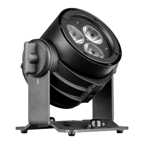
- Page 1 FLOORBAT PLUS MINI LED PROJECTOR 3x15W RGBW – IP65 Order code: SG FLBATPLUS MANUALE UTENTE USER MANUAL...
-
Page 2: Table Of Contents
ReL. 01-04/24 INDICE: 1. INTRODUZIONE p. 3 2. ISTRUZIONI DI SICUREZZA p. 4 3. APERTURA CONFEZIONE E CONTROLLO p. 6 4. CARICA DELLA BATTERIA p. 8 5. INSTALLAZIONE ED UTILIZZO ACCESSORI p. 9 6. COLLEGAMENTI E MODALITA’ DI FUNZIONAMENTO p. 23 7. -
Page 3: Introduzione
1. INTRODUZIONE Grazie per avere scelto un nostro prodotto! Vi preghiamo di fare riferimento alle istruzioni e alle avvertenze contenute nel presente manuale per l’utilizzo del dispositivo e di conservarlo per future consultazioni. Il presente manuale contiene informazioni riguardanti l’installazione e l’utilizzo del dispositivo. Le informazioni contenute in questo documento sono state attentamente redatte e controllate. -
Page 4: Istruzioni Di Sicurezza
2. ISTRUZIONI DI SICUREZZA Attenzione! Questo prodotto non è adatto ad un uso domestico. Leggere il presente manuale prima di installare e dare corrente all’apparecchiatura, seguire le precauzioni di sicurezza elencate di seguito ed osservare tutti gli avvertimenti indicati nel presente manuale e stampati sull’apparecchiatura. - Page 5 CLASSE DI PROTEZIONE IP65 Il dispositivo è protetto dalla penetrazione di polvere (prima cifra 6) e da getti d’acqua (seconda cifra 5). Apparecchio adatto per uso esterno. PROTEZIONE CONTRO LE SCOSSE ELETTRICHE Quando alimentato dalla rete elettrica attraverso l’alimentatore esterno, il dispositivo deve essere collegato ad un sistema di alimentazione dotato di un’efficiente messa a terra.
-
Page 6: Apertura Confezione E Controllo
3. APERTURA DELLA CONFEZIONE E CONTROLLO Aprire con cura la confezione, verificare il contenuto e assicurarsi che tutte le parti siano presenti e siano in buone condizioni. Nel caso in cui alcune parti non siano presenti o siano danneggiate, contattare immediatamente il proprio fornitore e conservare l’imballaggio per la verifica. - Page 7 5. Piedino regolabile 6. Connettore alimentatore esterno 12,6 VDC 7. Interruttore ON/OFF 8. Display + pulsantiera touch 9. Staffe per blocco cover 10. Indicatore stato wireless 11. Foro manopola M4x8 per fissaggio accessori e cover 12. Foro manopola M5x16 per fissaggio staffa Par...
-
Page 8: Carica Della Batteria
4. – CARICA DELLA BATTERIA 4.1 – CARICA ATTRAVERSO L’ALIMENTATORE DI RETE ESTERNO - Collegare l’apparecchio alla rete elettrica tramite l’apposito alimentatore esterno fornito a corredo - Il tempo di ricarica standard per un faro con livello della batteria del 5% è di circa 5 ore a proiettore spento 4.2 –... -
Page 9: Installazione Ed Utilizzo Accessori
(incluso nella confezione) 1. Inserire il filtro antiabbagliamento allineandolo con la parte alta sullo stesso lato del logo SAGITTER 2. Allineare le 3 scanalature presenti sul filtro, con i relativi dentini presenti sul proiettore 3. appena inserito il filtro, ruotare per circa 5 gradi in senso orario, in modo da bloccare le scanalature nei dentini. - Page 10 Filtro antiabbagliamento correttamente installato, con manopola di bloccaggio M4x8 correttamente inserita 5.2 – SFERA (venduta separatamente – codice SG FLBATPLUSGL1) La sfera è dotata di un filtro frost 80 gradi incluso, che può essere utilizzato facoltativamente in aggiunta ad essa, per rendere più uniforme l’illuminazione della stessa. Tale filtro deve essere inserito prima dell’inserimento della sfera 1.
- Page 11 FASE 1: montaggio filtro 80 gradi FASE 2: montaggio sfera Manopola di bloccaggio M4x8...
- Page 12 Sfera correttamente installata, con manopola di bloccaggio M4x8 correttamente inserita 5.3 – CILINDRO CM.11 (venduto separatamente – codice SG FLBATPLUSCY1) Il cilindro 11cm è dotato di un filtro frost 80 gradi incluso, che può essere utilizzato facoltativamente in aggiunta ad esso, per rendere più uniforme l’illuminazione dello stesso. Tale filtro deve essere inserito prima dell’inserimento del cilindro.
- Page 13 FASE 1: montaggio filtro 80 gradi FASE 2: montaggio cilindro cm.11 Manopola di bloccaggio M4x8...
- Page 14 Cilindro cm.11 correttamente installato, con manopola di bloccaggio M4x8 correttamente inserita 5.4 – CILINDRO CM.50 (venduto separatamente – codice SG FLBATPLUSCY2) Per il montaggio del cilindro cm.50 è possibile fare riferimento alle immagini relative all’installazione del cilindro cm.11, con la sola differenza che questo secondo cilindro non ha in dotazione il filtro frost 80°, per cui nel montaggio non deve essere considerata questa parte.
- Page 15 5.5 – STAFFA PAR (inclusa nella confezione) 1. Allineare la staffa ed il proiettore come nell’immagine seguente Foro M5 2. Sollevare il proiettore ed inserirlo nella staffa facendolo scorrere fino a quando il foro centrale M5, si allinea al relativo foro della staffa Fori da allineare 3.
- Page 16 4. A questo punto è possibile orientare il proiettore con la staffa e serrare le due manopole laterali per il bloccaggio 5.6 – COVER CROMATA (venduta separatamente – codice SG FLBATPLUSCCH) COVER BIANCA (venduta separatamente – codice SG FLBATPLUSCWH) 1. Capovolgere il proiettore appoggiandolo con la parte frontale su un piano orizzontale 2.
- Page 17 4. Allentare le 4 viti a brugola che tengono le alette mobili e far scorrere le alette verso l’esterno, in modo da inserirsi all’interno delle due feritoie della cover. Quando le alette saranno allargate al massimo, dovranno essere serrate le 4 viti a brugola per poter impedire il movimento delle alette stesse e quindi la caduta accidentale della cover.
- Page 18 Se oltre alla cover vengono installati il filtro antiabbagliamento, oppure la sfera, oppure il cilindro cm.11, o infine il cilindro cm.50, la manopola di bloccaggio M4x8 deve essere inserita obbligatoriamente anche in questi casi, in quanto essa è in grado di bloccare contemporaneamente sia la cover che l’eventuale accessorio.
- Page 19 ATTENZIONE !!! Alla fine del montaggio della staffa Pendant, controllare che le alette mobili non abbiano subito spostamenti e che quindi la cover sia ancora saldamente ancorata al proiettore. ATTENZIONE !!! Nella sospensione del proiettore con staffa Pendant, deve essere installato obbligatoriamente l’occhiello di sicurezza fornito in dotazione.
- Page 20 3. Posizionare la staffa pendant ed avvitarla con le due viti a brugola M4x15 fornite in dotazione 4. Rimuovere completamente il piedino regolabile…...
- Page 21 5. …ed avvitare, serrandolo a fondo, l’occhiello di sicurezza al quale poi agganciare una fune di sicurezza venduta separatamente. Il golfare deve essere utilizzato esclusivamente come occhiello di sicurezza. In caso di sospensione a soffitto, questo deve essere obbligatoriamente installato, per poter assicurare il proiettore con una fune di sicurezza ausiliaria venduta separatamente (PLH232 –...
- Page 22 5.7 – INSTALLAZIONE TRAMITE STAFFA PAR (inclusa nella confezione) Attraverso la staffa PAR, il proiettore può essere installato a pavimento in appoggio sui piedini in gomma, oppure sospeso su traliccio ATTENZIONE! E' OBBLIGATORIO il montaggio della fune di sicurezza (PLH232 – PLH248 vendute separatamente) nel caso in cui il prodotto sia appeso su truss.
-
Page 23: Collegamenti E Modalita' Di Funzionamento
6. – COLLEGAMENTI E MODALITA’ DI FUNZIONAMENTO 6.1 - COLLEGAMENTO ALLA LINEA DI ALIMENTAZIONE Quando alimentato dalla rete attraverso l’alimentatore esterno, il dispositivo deve essere collegato ad un sistema di alimentazione dotato di un’efficiente messa a terra. Inoltre, si consiglia di proteggere le linee di alimentazione dei prodotti dai contatti indiretti e/o da cortocircuiti verso massa utilizzando interruttori differenziali opportunamente dimensionati. - Page 24 E' necessario poi accoppiare il proiettore al trasmettitore seguendo le successive indicazioni: 1. Dopo aver acceso il proiettore ed il trasmettitore, se non ci sono nuovi trasmettitori a cui accoppiare, esso si accoppia automaticamente all'ultimo trasmettitore a cui era stato precedentemente accoppiato. 2.
- Page 25 7. Nel sottomenu OPERATE MODE – WIRELESS, selezionare LINK. Si avvierà la procedura di link tra il MASTER e tutti gli SLAVE 8. Nel sottomenu OPERATE MODE – CONTROL MODE, selezionare W-DMX o IRC a seconda che si vogliano impostare i programmi del master da display o da telecomando 9.
- Page 26 6.5 – FUNZIONAMENTO CON RADIOCOMANDO (incluso nella confezione) Impostando il proiettore in modalità IRC (OPERATE MODE – CONTROL MODE – IRC) il proiettore può essere controllato tramite il radiocomando fornito in dotazione. Impostazioni modalità di funzionamento: Automatico e velocità Sound e sensibilità Black-out Impostazioni singoli colori in modalità...
-
Page 27: Menu E Canali Dmx
7. – MENU E CANALI DMX 7.1 – MAPPA DEL MENU’ (evidenziati i valori di default) Level 1 Level 2 Level 3 Level 4 Description DMX Address 001 – 512 Impostazione indirizzo DMX W-DMX Controllo Wireless DMX Control Mode Controllo con telecomando IR Funzioni Link/Unlink con Link / Unlink proiettore in modalità... - Page 28 S-Curve Curva dimmer S 600Hz 1200Hz 2400Hz Rate Frequenza di refresh LED 4800Hz 9600Hz 15000Hz Retroilluminazione display: - ON: display sempre acceso Black Light ON/OFF - OFF: display spento dopo il tempo indicato nella funzione SCREEN TIME 10s…20s Screen Time Tempo di spegnimento display (default 15s) OFF = display non bloccato...
- Page 29 Temp XX °C Temperatura corrente Operate Time XXXH Ore totali di funzionamento XXXX : XXXXXXXX Codice RDM Note: (1) Dopo un reset default, tali valori vengono riportati tutti a 255 (2) La funzione FIND ME risulta utile nel caso in cui si debbano disporre i proiettori in luoghi bui, in cui potrebbe essere difficoltoso il ritrovamento in caso di scarica della batteria.
- Page 30 135 – 140 Color macro 24 141 – 146 Color macro 25 147 – 152 Color macro 26 153 – 158 Color macro 27 159 – 164 Color macro 28 165 – 170 Color macro 29 171 – 176 Color macro 30 177 –...
- Page 31 Modalità 12 canali Channel Function Value Description Master dimmer 000 – 255 Master dimmer 0%...100% 000 – 004 Nessuna funzione 005 – 063 Strobo da lento a veloce Strobo 064 – 191 Strobo random da lento a veloce 192 – 255 Flash strobo random da lento a veloce 000 –...
- Page 32 189 – 194 Color macro 33 195 – 200 Color macro 34 201 – 206 Color macro 35 207 – 212 Color macro 36 213 – 218 Color macro 37 219 – 224 Color macro 38 225 – 230 Color macro 39 231 –...
- Page 33 memorizzare) Battery Med (attendere 5 secondi per attivare e 151 - 160 memorizzare) 161 – 180 Nessuna funzione 181 – 185 Total reset (attendere 5 secondi per attivare) 186 – 205 Nessuna funzione Factory Reset (in combinazione con CH2=070 – attendere 206 –...
-
Page 34: Manutenzione
8. - MANUTENZIONE Per garantire ottime prestazioni, l’apparecchio deve essere pulito frequentemente. Scollegare l’apparecchio della corrente e lasciarlo raffreddare per almeno 35 minuti onde evitare il rischio di bruciature. Utilizzare un’aspirapolvere o compressore e una spazzola morbida o un panno per lenti per rimuovere la polvere depositata. -
Page 35: Dimensioni
10. - DIMENSIONI... -
Page 38: Introduction
1. - INTRODUCTION Thank You for choosing one of Our products! Please refer to the instructions and warnings contained in this user manual, please retain it for future reference. This manual contains information about the installation and use of the device. The information contained in this publication has been carefully prepared and checked. -
Page 39: Safety Instructions
2. - SAFETY INSTRUCTIONS Caution! This product is not suitable for household illumination. Please read this manual before installing and applying power to the equipment, follow the safety precautions listed below and observe all warnings in this manual and printed on. Please contact a PROEL distributor for assistance with any questions about how to activate the equipment safely. - Page 40 IP65 PROTECTION RATING The device is protected against the dust penetration (first digit 6) and against jets of water (second digit 5). Suitable for outdoor use. PROTECTION AGAIN ELECTRIC SHOCK When the projector is powered by the mains with its specific external adapter, it must be connected to a power supply system with efficient earthing.
-
Page 41: Opening And Control
3. - OPENING AND CONTROL Carefully open the package, check the content and make sure that all the parts are present and are in good condition. In cases where some parts are not present or are damaged, immediately contact Your supplier and retain the packaging for verification. WARNING! If the product has been exposed to drastic temperature changes, let the unit turned off until it reaches room temperature because the... - Page 42 5. Adjustable foot 6. connector for external adapter 12,6 VDC 7. Switch ON/OFF 8. Display + touch buttons 9. Mobile brackets for locking covers 10. Wireless status indicator 11. Hole for knob M4x8 for licking accessories and cover 12. Hole for knob M5x16 For locking Par bracket...
-
Page 43: Battery Charge
4. – BATTERY CHARGE 4.1 - CHARGE WITH CONNECTION TO THE MAINS - Connect the projector to the mains with its specific external adapter included in the carton - The standard time for battery charge when the level is 5%, is approximately 5 hours with projector OFF. -
Page 44: Installation And Use Of Accessories
5.1 – ANTIGLARE FILTER (included in the carton) 1. Insert the antiglare filter, aligning the highest part on the same side of the SAGITTER logo. 2. Align the 3 grooves on the filter with the relative teeth on the projector 3. - Page 45 Antiglare filter correctly installed, with M4x8 locking knob correctly fixed 5.2 – SPHERE (sold separately – code SG FLBATPLUSGL1) The sphere is equipped with an 80 degree frost filter included, which can be optionally used in addition to it, to make its lighting more uniform. This filter must be inserted before inserting the sphere 1.
- Page 46 STEP 1: installation 80 degrees filter STEP 2: installation shpere M4x8 locking knob...
- Page 47 Sphere correctly installed, with M4x8 locking knob correctly fixed. 5.3 – CYLINDER CM.11 (sold separately – code SG FLBATPLUSCY1) The cylinder cm.11 is equipped with an 80 degree frost filter included, which can be optionally used in addition to it, to make its lighting more uniform. This filter must be inserted before inserting the cylinder 1.
- Page 48 STEP 1: installation 80 degrees filter STEP 2: installation cylinder cm.11 M4x8 locking knob...
- Page 49 Cylinder cm.11 correctly installed, with M4x8 locking knob correctly fixed. 5.4 – CYLINDER CM.50 (sold separately – code SG FLBATPLUSCY2) For the assembly of the 50 cm cylinder it is possible to refer to the images relating to the installation of the 11 cm cylinder, with the only difference that this second cylinder is not supplied with the 80°...
- Page 50 5.5 – PAR BRACKET (included in the carton) 1. Align the bracket and the projector as in the following picture M5 hole 2. Lift the projector and insert it into the bracket, sliding it until the central M5 hole aligns with the relative hole in the bracket Holes to align...
- Page 51 4. Now it is possible to orient the projector with the bracket and tighten the two side knobs for locking. 5.6 – CHROME COVER (sold separately – code SG FLBATPLUSCCH) WHITE COVER (sold separately – code SG FLBATPLUSCWH) 1. Turn the projector upside down, placing it with the front part on a horizontal surface 2.
- Page 52 4. Loosen the 4 Allen screws that hold the movable brackets and slide them outwards, so as to fit inside the two slots on the cover. When the brackets are widened to the maximum, the 4 Allen screws must be tightened to prevent the movement of the brackets themselves and therefore the accidental fall of the cover.
- Page 53 If, in addition to the cover, the anti-glare filter, or the sphere, or the 11cm cylinder, or the 50cm cylinder, are installed, also in these cases the M4x8 locking knob must be inserted, as it is capable of block both the cover and any accessory at the same time. M4x8 locking knob, that locks, in this case, white cover and sphere...
- Page 54 WARNING !!! At the end of the assembly of the Pendant bracket, check that the mobile brackets were not moved and that the cover is therefore still firmly fixhed to the projector. WARNING !!! When the projector is suspended with the Pendant bracket, the safety eye ring supplied must be installed.
- Page 55 3. Put the pendant bracket and screw it with the two M4x15 Allen screws supplied 4. Totally remove the adjustable foot …...
- Page 56 5. … and screw, tightening it fully, the safety eye ring to which you can then connect a safety rope sold separately. The eyebolt must only be used as a safety eye ring. In the case of ceiling suspension, this must be installed in order to secure the projector with an additional safety rope sold separately (PLH232 –...
- Page 57 5.7 – INSTALLATION WITH PAR BRACKET (included in the carton) With the Par bracket the unit can be installed on the floor resting on the rubber feet, or suspended on a truss. WARNING! IT'S REQUIRED the mounting of the safety rope (PLH232 – PLH248) sold separately) in the case where the product is hung on a wall, ceiling or on a truss.
-
Page 58: Connection And Working Modes
6. – CONNECTIONS AND WORKING MODES 6.1 – CONNECTION TO THE MAINS When the projector is powered by the mains with its specific external adapter, it must be connected to a power supply system with a proper earth system. Moreover, it is recommended to protect power supply lines of the products from indirect contact and / or shorting to earth by using appropriately sized anti electrical shock switch. - Page 59 It is then necessary to link the projector with the transmitter following the following instructions: 1. After switching on the projector and the transmitter, if there are no new transmitters to which link it, the projector automatically pairs to the last transmitter to which it was previously linked.
- Page 60 7. In the submenu OPERATE MODE – WIRELESS, set LINK. The link process between the Master and all the Slaves will start. 8. In the submenu OPERATE MODE – CONTROL MODE, set W-DMX or IRC depending on whether you want to set the master programs from the display or IR remote control. 9.
- Page 61 6.5 – IR WORKING MODE By setting the projector in IRC mode (OPERATE MODE – CONTROL MODE – IRC) the projector can be controlled by using the IR remote controller included in the carton. Working modes settings: Auto mode and speed Sound and sensitivity Black-out Single color settings in manual mode...
-
Page 62: Menu And Dmx Channels
7. – MENU AND DMX CHANNELS 7.1 – MENU (highlighted the default values) Level 1 Level 2 Level 3 Level 4 Description DMX Address 001 – 512 DMX address setting W-DMX Control by Wireless DMX Control Mode Control by IRC Link / Unlink In case of Master Wireless... - Page 63 - OFF: display OFF after seconds indicated in SCREEN TIME function 10s…20s Screen Time Backlight display OFF time (default 15s) OFF = screen not locked 30s = screen locked after 30 Screen Lock OFF – 30s seconds. To unlock press and hold ENTER button for 10 seconds 050 –...
- Page 64 7.2 – DMX CHANNEL MODES 3-channels mode Channel Function Value Description Master dimmer 000 – 255 Master dimmer 0%...100% 000 – 004 No function 005 – 009 Color macro 1 010 – 014 Color macro 2 015 – 019 Color macro 3 020 –...
- Page 65 024 – 047 3000 K 048 – 071 3500 K 072 – 095 4000 K 096 – 119 4500 K 120 – 143 5000 K 144 – 167 6000 K 168 – 191 7000 K 192 – 215 8000 K 216 –...
- Page 66 005 – 009 Color macro 1 010 – 014 Color macro 2 015 – 019 Color macro 3 020 – 024 Color macro 4 025 – 029 Color macro 5 030 – 034 Color macro 6 035 – 039 Color macro 7 040 –...
- Page 67 192 – 215 8000 K 216 – 225 9000 K 226 – 255 10000 K 000 – 255 Red dimmer 0%...100% Green 000 – 255 Green dimmer 0%...100% Blue 000 – 255 Blue dimmer 0%...100% White 000 – 255 White dimmer 0%...100% 000 - 050 No function 051 –...
-
Page 68: Maintenance
8. - MAINTENANCE To ensure optimal performance, the unit must be frequently cleaned. Unplug the device from the mains and let it cool for at least 35 minutes to avoid the risk of burns. Use a vacuum cleaner or an air compressor and a soft brush or a lens cloth to remove the dust deposited. The lenses, like any other damaged part, must be replaced with original spare parts. -
Page 69: Dimensions
10. - DIMENSIONS...
Need help?
Do you have a question about the FLOORBAT PLUS and is the answer not in the manual?
Questions and answers