Table of Contents
Advertisement
Quick Links
Advertisement
Table of Contents

Related Manuals for tediselmedical ABITUS


Summary of Contents for tediselmedical ABITUS
- Page 1 ABITUS USER AND CLEANING MANUAL...
-
Page 2: Table Of Contents
Content Manufacturer ..........................4 Security information ........................4 2.1. Injury risk warnings ........................4 2.2. Warnings of risk of damage ..................... 4 2.3. Supplementary symbols used in the safety instructions ............5 2.4. Indication of additional information ..................5 2.5. Proper use of oxygen. - Page 3 5.6. Maximum payload capacity ....................22 Technical data ..........................24 6.1. Overall dimensions ........................ 24 6.2. Weight of the hanging system ....................25 Downpipes........................25 Suspended headboard. Main body ................25 Carousel. Extension arm ....................26 Service head ........................26 Accessories ........................
-
Page 4: Manufacturer
Address: C/ Sant Lluc, 69-81. 08918 - Badalona (Barcelona) SPAIN Tel. +34 933 992 058 Fax +34 933 984 547 tedisel@tedisel.com www.tediselmedical.com 2. Security information Important notes in these operating instructions are marked with graphic symbols and signal words. 2.1. Injury risk warnings Signal words such as DANGER, WARNING or CAUTION describe the degree of risk of injury. -
Page 5: Supplementary Symbols Used In The Safety Instructions
Refers to a potential hazard which, if not avoided, may cause NOTICE damage to the equipment. 2.3. Supplementary symbols used in the safety instructions Fire hazard Explosion hazard: warns of ignition of explosive gas mixtures. Dangerous voltage: warns about electric shocks that can cause serious injury or death. Failure of the roof support system Risk of collision 2.4. -
Page 6: Patient Environment
with oxygen! - Don't smoke! 2.6. Patient environment The dimensions in the figure below illustrate the minimum extent of the patient environment in an unrestricted area according to IEC 60601-1. Fig. 1 Minimum extent of the PATIENT ENVIRONMENT 2.7. Combination with products from other manufacturers. The suspension system is combined with the service head. -
Page 7: Risks
Read the Operating Instructions provided by the external manufacturer to obtain the necessary information for the operation of the end device. 3. Risks 3.1. Ga explosion s Oxygen becomes explosive when it comes into contact with oils, greases and lubricants. When in contact with oxygen in the air, medical gases may form an explosive or easily flammable gas mixture. -
Page 8: Risk Of Collision
3.6. Risk of collision In the event of a collision with other devices, walls or ceilings, the pendant system and service head may be damaged and important patient care systems may fail, after a collision, the service head and pendant system should be inspected for damage. 3.7. - Page 9 Protective earth (ground) Connection point for neutral conductor Nurse call button Direct lighting Indirect lighting Operating instructions Health Product Waste electrical equipment CE symbol Product code Unique identification code Serial number INF-015-EN 9 of 40 Version 0 | 01/12/2022...
- Page 10 Manufacturer Date of manufacture Reference to the instruction manual Damage to surfaces Fire hazard Danger of explosion Dangerous tension Notice NOTICE Risk of finger entrapment Warning WARNING Caution CAUTION INF-015-EN 10 of 40 Version 0 | 01/12/2022...
-
Page 11: Product Data
DANGER Danger 5. Product data This manual refers to the ABITUS model. This model is part of the SICS family. 5.1. Storage conditions The packaging of this type of product consists of two parts, the first one containing the suspended headrest (structural part of the equipment) and the second one corresponding to the service heads and/or trolleys. -
Page 12: Product Description
Electrical, voice and data services Nurse call The ABITUS units consist of three distinct parts, the structural part (downspouts), which is responsible for positioning the unit at the desired height, the suspended headrest and the service heads, which serves as a supply interface for energy consumers and also for the housing, storage and storage of medical devices and accessories. -
Page 13: Parts And Control Elements
Structure of connection to the slab Variable length to suit the height of the assembly Abitus main body attachment structure Fig.3 Parts. Downpipe For lengths up to 1.5m, a maximum pure tensile load of 4,500 kg per downpipe is defined. INF-015-EN... -
Page 14: Suspended Headboard. Main Body
5.4.1.2 Suspended headboard. Main body. Structural and functional element, attached to the downcomer, it is the chassis on which other accessory elements such as columns or trolleys can be fixed. It can also be used to house other elements such as lighting, terminal units for medical gases and vacuum, electrical sockets, etc. Fig. -
Page 15: Element Carrier Trolleys
5.4.1.4 Service head carousel A movable element that moves along a defined length within an ABITUS section and supports service heads and their accessories. These can be attached directly to the carousel (left image in figure 6) or via a 0.6m extension arm (right image in figure 6). The stroke of this carousel is defined by placing... - Page 16 Horizontal column Vertical column Fig. 7 Carousel detail for ABITUS with two columns and carousel with arm Fig. 8 Displacement of a carousel on ABITUS main body The actuators for the different brakes are located on the handles of the service head. See figure 9. For those configurations with direct service head on carousel, i.e.
-
Page 17: Service Heads
See section 8.4.4 of this manual. Fig. 9 Position of brake actuators on a service head The above figure shows the location of the brake actuators in a vertical service head (left picture in figure 9) and in a horizontal service head (right picture in figure 9). 5.4.1.5 Service heads There are two possible configurations for the media or service head, the most common of which is... - Page 18 accessories can be mounted. On the rear side, in the centre of figure 11, are the sockets or terminal units that serve as the supply interface for the power consumers that can be connected to the device. Depending on the height of the chassis, there are 3 standard sizes, on the right in figure 11. Please consult the manufacturer for special heights (*).
-
Page 19: Other Service Head Features
5.4.1.6 Other service head features 1. Treatment and finishing Aluminium profiles can be processed either raw and then polished or anodised. Finishes can be epoxy paint or antibacterial paint. The standard colour used is matt white, but any other colour is possible according to project specifications. -
Page 20: Accessories
8. Gas intakes Possibility of installation and supply of gas inlets with ISO and USA standards. ISO standards include the following types: DIN 13260-2, AFNOR NF S 90-116, SS 875 24 30, BS 5682:2015, CM, CZ, ENV 737-6 EN 15908, UNI 9507, SDEGA EN ISO 9170-2. Within the US standards are the following standards: ALLIED/CHEMETRON, DISS, OHIO/OHMEDA, PURITAN/BENNETT and OXEQUIP/MEDSTAR. -
Page 21: Maximum Load Capacity
technical rails for attaching accessories Loading tray Chest of drawers (single) Side tubes for attachment of other accessories Fig.14 Fittings on vertical service head Figure 15 shows an example of an element tray and another tray with an individual drawer unit and two vertical tubes which, in turn, will hold more accessories. -
Page 22: Maximum Payload Capacity
In the case of equipping the suspended headboard with trolleys, the load is always counted as applied on the axis of rotation of the trolleys as shown in figure 17. The maximum load per main head section is 600 kg. This load includes the payload capacity of the systems suspended from the suspended head end body as well as their own weight. - Page 23 Not including own weight of trays and/or drawers or other accessories intended to hold more items. In the example illustrated in figure 18, there is an ABITUS assembly with column and extension arm. The maximum payload is 100 kg after subtracting the dead weight of the extension arm and the...
-
Page 24: Technical Data
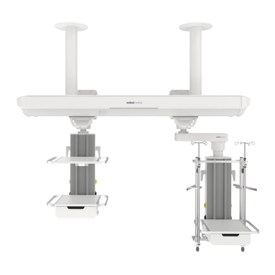
6. Technical data 6.1. Overall dimensions Below is an ABITUS suspension system with a vertical service head with extension arm, a horizontal service head and a trolley. Please note that the configuration of your hanging system may differ from this illustration. Please consult the manufacturer for special lengths (*). -
Page 25: Weight Of The Hanging System
If no restriction is specified, they are configured as shown in figure 20. See the manufacturing and installation drawing accompanying the equipment. Fig.20 Swivel range for extension arms on an ABITUS section 6.2. Weight of the hanging system The weight of the system does not include gas hoses, inserted power cables, ceiling plates, drop pipes and optional accessories. -
Page 26: Carousel. Extension Arm
Carousel. Extension arm Carousel ...........................18kg Carousel with extension arm ...................33kg Service head TDSHV vertical service head (750mm) ................18kg TDSHV vertical service head (1000mm) ................21kg TDSHV vertical service head (1250mm) ................25kg TDSHH horizontal service head (600mm) ...............18kg Accessories Item trolley (trapeze 300mm) ..................16Kg Item trolley (trapeze 500mm) ..................16.5Kg Item trolley (trapeze 700mm) ..................17Kg Tray on vertical service head ..................9kg... -
Page 27: Electrical Data
ARD and ICU. 8. Use of equipment ABITUS devices are intended for continuous operation. The specifications of the individual functional elements of the equipment must be observed when using the equipment. (A) Electrical, voice and data circuits. -
Page 28: Product Preparation
(B) Nurse call (C) Lighting (D) Gas intakes There may be actuators for switching on modules of the lighting modules in the room in which the equipment is installed. See product and installation drawing supplied with the equipment. NOTICE: Details of the elements and their characteristics can be found in the product definition drawing. -
Page 29: Training
8.3. Training Personnel using ABITUS equipment must be properly trained and qualified by the customer. The equipment must only be USED by authorised personnel. Persons who: 1. have undergone medical training and are duly registered (at those levels where legal provisions make such registration necessary). -
Page 30: Adjustment Of The Swing Brakes
Be sure to tighten the brake screws at the carousel more than at the pivot point of the service head. This facilitates the correct positioning of the service head in relation to the new position of the extension arm. 8.4.1.1 Adjustment of the swing brakes 1. -
Page 31: Adjustment Of Limit Switches For Carousels And Carriages
Adjustment of limit switches for carousels and carriages The carousels and carriages of ABITUS equipment can slide freely over the entire length of the main body section on which they are installed. It is necessary to limit their travel in order to ensure that these elements do not conflict with the patient and operator space. -
Page 32: Mechanical Brake Release For Trolleys For Element Carriers
Fig.26 Carriage brake release actuators for ABITUS • To move the trolley to another position within the main body section of the ABITUS, pull the handle (A) downwards to release the travel brake of the unit and, without releasing it, move... -
Page 33: Pneumatic Brake Release For Carousel
Pneumatic brake release for carousel The pneumatic brakes for the ABITUS carousels are factory set. These brakes stop the carousels from moving on the guides of the main body as well as the rotation of the extension arm and/or the service head around its axis. -
Page 34: Cleaning
Fig.28 Unlocking the swing and travel brakes of ABITUS armless columns 9. Cleaning Perform this operation with slightly moist cleaning instruments to ensure that no liquid enters the equipment. Since no part or component of the system is invasive, sterilisation is not necessary. -
Page 35: Disinfection
WARNING: Parts of the pendant system and adaptations are made of plastic. Solvents can dissolve plastic materials. Strong acids, bases and agents with an alcohol content of more than 60 % can cause plastic materials to become brittle. Dislodged particles may fall into open wounds. -
Page 36: User Information On Warnings
11. User information on warnings Under no circumstances shall the user remove any part of the equipment enclosure to carry out checks. 11.1. Lighting problems In the event of a fault or malfunction in the lighting systems, check the ignition from all intended actuators. -
Page 37: Reference Standards
Equipment intended for continuous operation. 13.2. Reference standards The device complies with the safety requirements of the following standards and directives: ISO11197: Medical supply units IEC 60601-1: Medical electrical equipment. General requirements for basic safety and essential performance. IEC 60601-1-2: Medical electrical equipment. Part 1-2. General requirements for basic safety and essential performance. - Page 38 Interference Test level according Level of compliance Environment/Guidelines resistance to IEC 60601 Static Electric ±8 kV contact ±8 kV contact Floors should be made of Discharge (ESD) discharge discharge wood, concrete or ceramics. If according to IEC 15 kV aerial 15 kV aerial discharge the floor is covered with a 61000-4-2...
- Page 39 Short interruptions 100% for 5 s The quality of the supply of the supply voltage should be typical for a voltage in Remark: commercial or hospital accordance with UN is the AC mains environment. the standard voltage before If the user of the roof supply IEC 61000-4- 11 applying the test unit requires continuous...
- Page 40 Transmitter power rating Safety distance depending on emission frequency Environment/Guidelines 150 kHz to 80 80 MHz up to 800 MHz up to 800 MHz 2.5 GHz D = 1,2 P D = 1,2 P D = 2, 3 P 0,01 0,12 0,12 0,23...
Need help?
Do you have a question about the ABITUS and is the answer not in the manual?
Questions and answers