Table of Contents
Advertisement
Quick Links
Advertisement
Table of Contents

Summary of Contents for tediselmedical N270
- Page 1 N270 MAINTENANCE MANUAL...
-
Page 2: Table Of Contents
Content Manufacturer ........................4 Security information ......................4 2.1. Injury risk warnings ..................... 4 2.2. Warnings of risk of damage ..................4 2.3. Additional symbols used in the safety instructions ............ 5 2.4. Indication of additional information ................5 2.5. Proper use of oxygen. - Page 3 Regulations ........................16 9.1. Team ranking ......................16 9.2. Reference standards ....................16 9.3. Electromagnetic compatibility.................. 17 INF- 202-EN 3 of 19 Version 0 | 01/12/2022...
-
Page 4: Manufacturer
Address: C/ Sant Lluc, 69-81. 08918 - Badalona (Barcelona) SPAIN Tel. +34 933 992 058 Fax +34 933 984 547 tedisel@tedisel.com www.tediselmedical.com 2. Security information Important notes in these operating instructions are marked with graphic symbols and signal words. 2.1. Injury risk warnings Signal words such as DANGER, WARNING or CAUTION describe the degree of risk of injury. -
Page 5: Additional Symbols Used In The Safety Instructions
Refers to a potential hazard which, if not avoided, may cause NOTICE damage to the equipment. 2.3. Additional symbols used in the safety instructions Fire hazard Explosion hazard: warns of ignition of explosive gas mixtures. Dangerous voltage: warns about electric shocks that can cause serious injury or death. -
Page 6: Risks
3. Risks 3.1. Gas explosion Oxygen becomes explosive when it comes into contact with oils, greases and lubricants. When in contact with oxygen in the air, medical gases may form an explosive or easily flammable gas mixture. The equipment is not suitable for use in environments containing flammable mixtures of anaesthetics with high concentrations of oxygen or nitrous oxide. - Page 7 Equipotentiality Protective earth (ground) Connection point for neutral conductor Nurse call button Direct lighting Indirect lighting Operating instructions Health Product Waste electrical equipment CE symbol Product code Unique identification code INF- 202-EN 7 of 19 Version 0 | 01/12/2022...
- Page 8 Serial number Manufacturer Date of manufacture Reference to the instruction manual Damage to surfaces Fire hazard Danger of explosion Dangerous tension NOTICE Notice Risk of finger entrapment Warning WARNING INF- 202-EN 8 of 19 Version 0 | 01/12/2022...
-
Page 9: Product Data
DANGER 5. Product data This manual refers to the N270 model. This model is part of the SICA family. 5.1. Storage conditions The individual packaging of this type of product consists of a bubble wrap on the inside and a cardboard box on the outside. -
Page 10: Purpose Of The Product
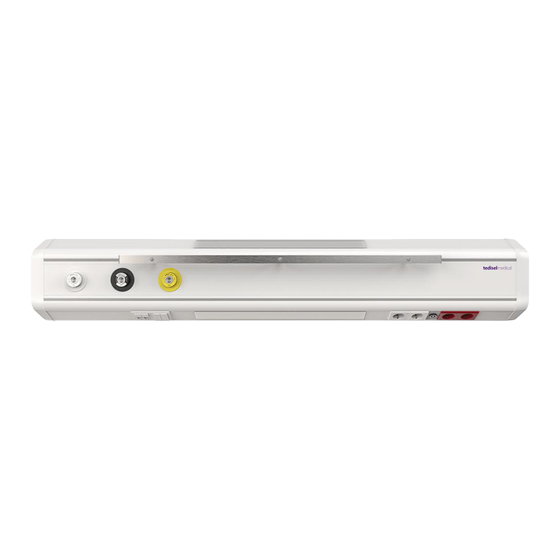
5.4. Purpose of the product These systems have three main distinct functions within the hospital: Medical gas services Electrical, voice and data services Lighting Nurse call They consist of a chassis made of aluminium profiles, which integrates the electrical equipment, call, voice and data systems, and installation and channelling of medical gas outlets. -
Page 11: Removal Of Top And Bottom Covers
Fig.1 Removal of upper and lower diffusers • Put the diffusers back on the equipment and press them into position until the clipping sound is heard. 6.2.2. Removal of top and bottom covers • Remove the diffusers as described in the previous chapter. You now have access to the side of the upper ①... -
Page 12: Removal Of Central Cover
6.2.3. Removal of central cover • Remove the front cover ② using the suction cup ① as shown in figure 3 to reveal the pre- installed gas inlets on the device. Fig.3 Removing the central cover of the gas rail •... -
Page 13: Replacement Of Led Strips And Drivers In Lighting Module S
IT and communications staff. 6.5. Replacement of LED strips and drivers in lighting module s If the lighting modules of the N270 system are malfunctioning, both the LED strips ② and the controllers ① must be replaced. -
Page 14: Envelopes And Structural Elements
• Connect the power supply of the controller ① back to the terminal strip. • Connect the power supply quick connector of the newly installed LED strip ②. • Check that the lighting module is fixed in position. • Power up the lighting circuit and perform a test run to check that the lighting module switches on and off. -
Page 15: Inspection Plan
6.7. Inspection plan 7. Cleaning Perform this operation with slightly moist cleaning instruments to ensure that no liquid enters the equipment. Since no part or component of the system is invasive, sterilisation is not necessary. Do not use abrasive or very hard cleaning agents that may cause damage to the exterior coatings, such as disinfectants containing sodium hypochlorite, which is highly corrosive to aluminium. -
Page 16: Waste Management
1. Dilute 4 pulses of the valve supplied by the manufacturer per 5 litres of water. 2. Spray the compound on the product and let it react for 15 minutes. 3. Remove with water or soap solution with a wrung out cloth. Switch off the power supply Contact with live parts can cause an electric shock. - Page 17 9.3. Electromagnetic compatibility. According to EN 60601-1-2:2015 this equipment is intended for use in the electromagnetic environment specified below. The user of this equipment must satisfy himself that it is being used in such an environment. Interference emission Compliance Comment measurements HF emissions according to Group 1...
- Page 18 Overvoltage (wave) ±1 kV phase-to- ±1 kV phase-to-phase The quality of the supply according to IEC phase voltage voltage voltage should be typical for a 61000-4- 5 ±2 kV phase to ±2 kV phase to ground commercial or hospital ground voltage voltage environment.
- Page 19 Interference resistance Level of verification according to Level of Environment/Guidelines IEC 60601 compliance HF interference AM 1KHz modulation 3 Vrms 150 kHz to 80 MHz 3 Vrms induced by Depth 80% Depth 80% 6 Vrms ISM band 6 Vrms IEC 61000-4-6 Depth 80% Depth HF interference induced by...


Need help?
Do you have a question about the N270 and is the answer not in the manual?
Questions and answers