Table of Contents
Advertisement
Quick Links
Advertisement
Table of Contents

Related Manuals for tediselmedical S-COLUMN


Summary of Contents for tediselmedical S-COLUMN
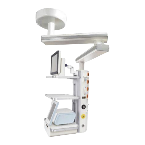
- Page 1 S- COLUMN MAINTENANCE MANUAL...
-
Page 2: Table Of Contents
Content Manufacturer ........................4 Security information ......................4 2.1. Injury risk warnings ..................... 4 2.2. Warnings of risk of damage ..................4 2.3. Additional symbols used in the safety instructions ............ 5 2.4. Indication of additional information ................5 2.5. Proper use of oxygen. - Page 3 6.5. Maintenance plan ..................... 22 Cleaning ..........................25 Waste management ......................26 Regulations ........................26 9.1. Team ranking ......................26 9.2. Reference standards ....................26 9.3. Electromagnetic compatibility.................. 26 INF-242-EN 3 of 29 Version 0 | 01/12/2022...
-
Page 4: Manufacturer
Address: C/ Sant Lluc, 69-81. 08918 - Badalona (Barcelona) SPAIN Tel. +34 933 992 058 Fax +34 933 984 547 tedisel@tedisel.com www.tediselmedical.com 2. Security information Important notes in these operating instructions are marked with graphic symbols and signal words. 2.1. Injury risk warnings Signal words such as DANGER, WARNING or CAUTION describe the degree of risk of injury. -
Page 5: Additional Symbols Used In The Safety Instructions
Refers to a potential hazard which, if not avoided, may cause NOTICE damage to the equipment. 2.3. Additional symbols used in the safety instructions Fire hazard Explosion hazard: warns of ignition of explosive gas mixtures. Dangerous voltage: warns about electric shocks that can cause serious injury or death. Failure of the roof support system Risk of collision 2.4. -
Page 6: Patient Environment
- Open fire, red-hot objects and open light are not allowed when working. with oxygen! - Don't smoke! 2.6. Patient environment The dimensions in the figure below illustrate the minimum extent of the patient environment in an unrestricted area according to IEC 60601-1. Fig. -
Page 7: Risks
of conformity with Article 22 of the Medical Devices Regulation (EU) 2017/745 shall be provided. Read the Operating Instructions provided by the external manufacturer to obtain the necessary information for the operation of the end device. 3. Risks 3.1. Ga explosion s Oxygen becomes explosive when it comes into contact with oils, greases and lubricants. -
Page 8: Symbols Used
4. Symbols used Applicable part B Earth (mass) Equipotentiality Protective earth (ground) Connection point for neutral conductor Nurse call button Direct lighting Indirect lighting Operating instructions Health Product Waste electrical equipment INF-242-EN 8 of 29 Version 0 | 01/12/2022... - Page 9 CE symbol Product code Unique identification code Serial number Manufacturer Date of manufacture Reference to the instruction manual Damage to surfaces Fire hazard Danger of explosion Dangerous tension Notice INF-242-EN 9 of 29 Version 0 | 01/12/2022...
-
Page 10: Product Data
Danger 5. Product data This manual refers to the S-COLUMN model. This model belongs to the UMOS family. 5.1. Storage conditions The individual packaging of this type of product consists of a bubble wrap on the inside and a cardboard box on the outside. -
Page 11: Service Life
Recommended humidity range: 30 % to 75 %. Atmospheric pressure: 700 hPa to 1,060 hPa 5.3. Service life The service life of the UMOS family of products is determined by the service life of the medical gas intakes it incorporates, which is 8 years. 5.4. -
Page 12: Opening Of The Side Covers Of A Service Head
Built-in components from third party manufacturers must be inspected and maintained as prescribed in the corresponding Operating Instructions. 6.2.1. Opening of the side covers of a service head. To carry out the operations described in sections 6.4 and 6.5 of this manual, you will need to fold down the service head covers. -
Page 13: Structural And Movement Check
6.3. Structural and movement check A complete inspection of the entire suspension system shall be carried out, adjusting all parameters that deviate from those initially foreseen. Carry out a visual inspection to detect if any item is not properly fixed and there are no deformed or damaged items. -
Page 14: Adjustment Of The Mechanical Brake On The Arms
1. Rotate the extension arm or console tube to the desired end stop position and then insert the pivot stop ① and secure it by means of the M5x16 DIN 912 socket head cap screws ②. Make sure that the stop is firmly in place. The extension arm or drop tube can be rotated until the stop ①... -
Page 15: Adjustment Of The Mechanical Brake On The Drop Tube
The mechanical brakes (friction brakes) hold the extension arm (2) in any set position. Adjust the braking force in such a way that the extension arm (2) remains stable in any position and can still be adjusted conveniently. If the brakes are not adjusted correctly, the extension arm may automatically move in an uncontrolled manner. -
Page 16: Procedure For Inspection And Replacement Of Flexible Hoses For Medical Gases
Use a suitable Allen screwdriver. 1. To increase the braking force, insert the flat screwdriver into the brake screws ① and turn it clockwise to the right. 2. To reduce the braking force, insert the flat screwdriver into the brake screws ① and turn it to the left (counterclockwise). - Page 17 C) Feel the connections to confirm that there is no slippage or unnecessary movement. Leak Detection: Biannual Soap solution, brush or paintbrush A) Prepare a soap solution in a container. B) Using a brush, apply the solution to the hose connections.
-
Page 18: Replacement Of Flexible Hoses For Medical Gases
Additional note: Be sure to follow all relevant safety regulations and recommendations. It is essential that personnel involved in these tasks are properly trained and wear personal protective equipment. 6.4.1. Replacement of flexible hoses for medical gases The gas hoses are pre-assembled on the Service Head. They must be replaced every 8 years in order to guarantee the correct functioning of the equipment. - Page 19 Fig. 6 Hose routing through the pendant system Make the connection of the new hoses at the point of origin (interface plate). Then reassemble the service head. Route the service head without exerting tension on the supply hoses ①. ...
- Page 20 Check hoses and lines for dirt and clean them with oil-free air. Attach a hose clamp to the gas supply hose, remove the sealing plug and push the hose into the correct gas supply outlet. Up to 3 gas supply hoses and up to 2 vacuum hoses can be connected to one gas valve using Y- connectors.
- Page 21 Fig. 18 Example of connection of gas hoses and anaesthesia gas evacuation systems Perform a gas type test by following these 5 points: 1. gas outlets and marking according to EN ISO 9170-1 or EN ISO 9170-2 2. Leakage according to EN ISO 11197 3.
-
Page 22: Maintenance Plan
6.5. Maintenance plan Item to be Description Periodicity Method of inspection inspected Structure Ensuring strength and load- Annual Visual inspection for signs of wear bearing capacity*. or corrosion Check condition and robustness Ensure that the spine remains Annual Visual inspection and stability Service Column firm and in position*. - Page 23 Flexible gas hoses Overhaul and status check*. Biannual Leak detection. It is recommended to See section 6.4 Inspection and disconnect the Replacement Procedure for equipment electrically before Flexible Hoses for medical gases. proceeding with the overhaul. Replacement of Replacement of flexible gas 8 years See point 6.4.1 Replacement of hoses*.
- Page 24 Electrical hoses Review and check of status and Annual Visual inspection and functional functionality*. test. Check connections, and and data correct signalling. It is recommended to disconnect the Check according to applicable equipment electrically before regulations. proceeding with the overhaul. See paragraph 6.2.1 Opening the side covers of a previously specified service head.
-
Page 25: Cleaning
The specific value of the load will depend on the specifications detailed in the Equipment. (3) Use of the multimeter: It shall be used to verify that electrical outlets and related components are operating correctly. With it, values such as voltage (to ensure that the sockets are providing the correct voltage), resistance (to identify possible faults or short circuits) and continuity (to ensure that circuits are complete and there are no interruptions) can be measured. -
Page 26: Waste Management
8. Waste management Applies WEE2012/19 and RoHS directive 2011/65/EU, amendment 2015/863/EU. The equipment has electrical and electronic components, so it cannot be disposed of as organic waste, but as electrical/electronic waste. 9. Regulations 9.1. Team ranking According to the new MDD regulation 93/42/EEC on medical devices, this product family is classified as: Class IIb, by Annex II, excluding section 4, rule 11. - Page 27 HF emissions according to The roof supply unit is suitable for use in non- Class A CISPR 11 standard domestic installations and in installations that are Harmonic emissions Class A directly connected PUBLIC SUPPLY according to the standard NETWORK, which also supplies residential...
- Page 28 UN is the AC mains power supply interruptions, it voltage before is recommended to supply the applying the test roof supply unit from a device level. with an uninterruptible power supply or a battery. Short interruptions 100% for 5 s The quality of the supply of the supply voltage should be typical for a...
- Page 29 Transmitter power rating Safety distance depending on emission frequency Environment/Guidelines 150 kHz to 80 80 MHz up to 800 MHz up to 800 MHz 2.5 GHz D = 1,2 P D = 1,2 P D = 2, 3 P 0,01 0,12 0,12 0,23...
Need help?
Do you have a question about the S-COLUMN and is the answer not in the manual?
Questions and answers