Advertisement
Quick Links
Advertisement

Related Manuals for NCR SelfServ Checkout R6L


Summary of Contents for NCR SelfServ Checkout R6L
- Page 1 Kit Instructions R6L Upgrade, Full Size Core 7350-K970 Issue D...
- Page 2 NCR, therefore, reserves the right to change specifications without prior notice. All features, functions, and operations described herein may not be marketed by NCR in all parts of the world. In some instances, photographs are of equipment prototypes. Therefore, before using this document, consult with your NCR representative or NCR office for information that is applicable and current.
-
Page 3: Revision Record
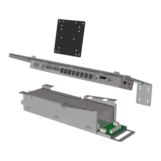
RevisionRecordK970 Revision Record Issue Date Remarks Dec 2017 First issue Feb 2018 • Updated the artwork and the parts list under Kit Contents • Reorganize the sequence of the Installation Procedures • Modified the Installing the 7360 I/O Box Nov 2018 • Updated the Cover Page •... - Page 5 Pocono E-Box unit to 7350 R6 Lite with the following components: • 7360 I/O Box • 7360 Power Supply • Display Bracket for NCR RealPOS XR7 (7702) Note: The 7350-K970 R6 Lite Upgrade Kit is not certified for installation on units...
-
Page 6: Kit Contents
7350-K970 R6L Upgrade, Full Size Core Kit Contents The R6L Upgrade, Full Size Core Installation Kit contains the following: Part Number Description 497-0528740 7350-K970 Kit - R6 Lite Upgrade, Full Size Core 009-0028273 Power Supply - Switch Mode – 600W +24V 497-0519618 Power Supply Bracket - R5 009-0006593... - Page 7 497-0513228 Label, Display Connector Ports 497-0519643 Cable - MEEI Adapter, with Loopback, 12 in (0.3 M) 497-0511101 Lane Light Graphics Label – NCR FastLane 497-0474154 Cable - 7702 Power, 24 V,3500 mm 497-0502540 Cable Assembly, Power Switch Jumper, 8006 497-0507921...
-
Page 8: Installation Procedures
Installing the 7360 I/O Box on page 15. Installing the System Power Supply on page 21. Installing the NCR 7702 Terminal Display on page 26. Note: To purchase an NCR 7702 Terminal Display, contact an NCR Customer Representative. Routing I/O Box Cables on page 31. Routing and Sorting Cables on page 32. - Page 9 7350-K970 R6L Upgrade, Full Size Core Removing the Touch Display In order to upgrade an existing NCR SelfServ Checkout (7350) unit to R6 Lite, the Touch Display must be removed and replaced with an NCR 7702 Terminal Display. To remove the existing Touch Display from the NCR SelfServ Checkout unit, follow these steps: Note: To purchase an NCR 7702 Terminal Display, contact an NCR Customer...
- Page 10 5. Close the Upper Cabinet Door. 6. Lift the Touch Display with the mounting bracket off the unit. Note: Replace the Touch Display with the NCR 7702 Terminal Display. To install the NCR 7702 Terminal Display, refer to Installing the NCR 7702 Terminal Display page 26.
- Page 11 7350-K970 R6L Upgrade, Full Size Core 3. If the VGA cable cannot get through the opening, remove the four wingnuts and then remove the cable. Note: Do not remove the Supervisor Switch/Cable. 4. Replace the four wingnuts. 5. Remove and discard the Display cables. For more information, refer to Removing and Sorting Cables on page 11.
- Page 12 7350-K970 R6L Upgrade, Full Size Core Removing the E-Box To remove the E-Box from the NCR SelfServ Checkout unit, follow these steps: 1. Turn off the NCR SelfServ Checkout software and hardware systems. 2. Open the Upper Cabinet Door. 3. Remove the Scanner and disconnect the cable from the E-Box.
- Page 13 6. Tilt the E-Box Bracket forward to easily access the cables. 7. Disconnect cables from the E-Box. 8. Slide E-Box forward to disengage the clips and then lift the unit off the bracket and out of the NCR SelfServ Checkout unit.
- Page 14 7350-K970 R6L Upgrade, Full Size Core Removing the 7350 Cooling Fan To remove the 7350 cooling fan, follow these steps: 1. Remove four nuts securing the cooling fan to the side of the Upper Cabinet. 2. Remove the cooling fan from the side of the Upper Cabinet. 3.
- Page 15 7350-K970 R6L Upgrade, Full Size Core Removing and Sorting Cables To remove and sort cables from the existing NCR SelfServ Checkout unit in order to prepare it for the R6 Lite components, follow these steps: 1. Remove 7350 components that must be replaced with R6 Lite components.
- Page 16 7350-K970 R6L Upgrade, Full Size Core 5. Pull out the cables from the back panel. 6. Remove all cable ties securing the cables. 7. Remove and discard the following cables from the bundle: • Display Cables • Cooling Fan Power Cable 8.
- Page 17 To install the mounting bracket to the Display, follow these steps: 1. Place the NCR 7702 Terminal Display on a flat surface with the back facing up. 2. Attach the mounting bracket to the back fo the Display using four screws, as shown below.
- Page 18 4. Do any of the following: • Install the 7360 I/O Box. For more information, refer to Installing the 7360 I/O Box on the facing page. • Install the NCR 7702 Terminal. For more information, refer to Installing the NCR 7702 Terminal Display on page 26...
- Page 19 7350-K970 R6L Upgrade, Full Size Core Installing the 7360 I/O Box To install the 7360 I/O Box, follow these steps: 1. Remove the existing 7350 components that need to be replaced. Note: To upgrade to R6 Tri–Light/Lane Light, refer to the 7350-K971 R6 Tri– Light/Lane Light Upgrade instructions.
- Page 20 7350-K970 R6L Upgrade, Full Size Core 3. Slide the I/O Box assembly to the left to engage the mounting hooks on the cabinet frame and then secure using two screws. 4. Connect the cables as shown in the images below. Side Cables Note: Use an Adapter Cable for the MEEI Controller Box cable before plugging in to the I/O Box.
- Page 21 7350-K970 R6L Upgrade, Full Size Core Front Cables 5. Do any of the following: • Install the system power supply. For more information, refer to Installing the System Power Supply on page 21 • Route the I/O Box cables. For more information, refer to Routing I/O Box Cables on page 31.
- Page 22 7350-K970 R6L Upgrade, Full Size Core Adjusting Tri–Light/Lane Light Jumper Settings to +24V The R6 Tri–Light/Lane Light is powered by +24Vdc through the 7360 I/O Box. To adjust the jumper settings, follow these steps: 1. Remove all cables from the 7360 I/O Box. Tip: Mark all cables as to where they are connected to easily reconnect them.
- Page 23 7350-K970 R6L Upgrade, Full Size Core 4. On the I/O Board, remove the jumper and set it on Pin 5 and Pin 6 as shown in the image below. Each jumper setting corresponds to a specific Tri–Light/Lane Light. • +24Vdc—Powers the R6 Tri–Light/Lane Light. •...
- Page 24 7350-K970 R6L Upgrade, Full Size Core • Secure two RS232 Ports to the I/O Box using four screws. 6. Install the I/O Box to the SelfServ Checkout unit by securing it to the I/O Box Mounting Plate using one nut.
- Page 25 7350-K970 R6L Upgrade, Full Size Core Installing the System Power Supply To install the System Power Supply, follow these steps: 1. Remove the existing 7350 components that need to be replaced. 2. Attach the System Power Supply to the Power Supply mount and then secure with a locking screw.
- Page 26 7350-K970 R6L Upgrade, Full Size Core 3. Connect the jumper to the System Power Supply. 4. At the back of the Sytem Power Supply, connect the power cable. Ensure the cable is secured to the Retainer Clip.
- Page 27 7350-K970 R6L Upgrade, Full Size Core 5. Slide the System Power Supply on the E-Box bracket and then secure with one nut. Note: The System Power Supply chassis has hooks on the bottom that are used to hinge the device to the cabinet. 6.
- Page 28 7350-K970 R6L Upgrade, Full Size Core 8. Do any of the following: • Install the NCR RealPOS XR7 (7702) Display. For more information, refer to Installing the NCR 7702 Terminal Display on page 26. • Route the System Power Supply cables. For more information, refer to...
- Page 29 7350-K970 R6L Upgrade, Full Size Core Routing System Power Supply Cables To route the System Power Supply cables, follow these steps: 1. Install the System Power Supply. For more information, refer to Installing the System Power Supply on page 21. 2. Secure the cables to the System Power Supply chassis using cable ties as shown in the image below.
- Page 30 7350-K970 R6L Upgrade, Full Size Core Installing the NCR 7702 Terminal Display To install the NCR 7702 Terminal Display, follow these steps: Note: To purchase an NCR 7702 Terminal Display, contact an NCR Customer Representative. 1. Remove 7350 components that must be replaced with R6 Lite components.
- Page 31 7350-K970 R6L Upgrade, Full Size Core 6. Secure the Display on the Upper Cabinet Door using four nuts. 7. Install the Display Connector Ports label.
- Page 32 7350-K970 R6L Upgrade, Full Size Core 8. Connect cables to the terminal. 9. Route the Display cables. For more information, refer to Routing NCR 7702 Terminal Display Cables on the facing page. 10. Install R6 Lite components. For more information, refer to the following procedures: Installing the 7360 I/O Box on page 15.
- Page 33 7350-K970 R6L Upgrade, Full Size Core Routing NCR 7702 Terminal Display Cables To route the Display cables in the NCR SelfServ Checkout unit, follow these steps: 1. Open the Upper Cabinet Door. 2. Install the Terminal Display. For more information, refer to Installing the NCR 7702...
- Page 34 7350-K970 R6L Upgrade, Full Size Core 4. Using cable loops, route the following cables from the back of the unit along the side of the Core Cabinet, as shown below. Note: The Supervisor Button cable is also routed through the cable loops. 5.
- Page 35 7350-K970 R6L Upgrade, Full Size Core Routing I/O Box Cables To route the I/O Box cables in the NCR SelfServ Checkout unit, follow these steps: 1. Install the I/O Box. For more information, refer to Installing the 7360 I/O Box page 15.
- Page 36 7350-K970 R6L Upgrade, Full Size Core Routing and Sorting Cables To route the cables in the R6 Lite unit, follow these steps: 1. Install all R6 Lite components. 2. Remove and sort existing 7350 cables. For more information, refer to Removing and Sorting Cables on page 11.
- Page 37 7350-K970 R6L Upgrade, Full Size Core 4. If R6 Lite cables are not yet routed in the unit, do the following: • Route the Display cables. For more information, refer to Routing NCR 7702 Terminal Display Cables on page 29. • Route the I/O Box cables. For more information, refer to Routing I/O Box Cables on page 31.
- Page 38 7350-K970 R6L Upgrade, Full Size Core 6. Place additional cables that cannot be bundled properly in the lower section of the cabinet as shown in the image below. 7. Install the back panel cover to the NCR SelfServ Checkout unit.
- Page 39 7350-K970 R6L Upgrade, Full Size Core Installing Lane Light Label To install the label on each side of the Lane Light, follow these steps: 1. Remove the Tri-Light/Lane Light assembly, if necessary. 2. Wipe any dust or dirt on the surface of both sides of the Lane Light. 3.
- Page 40 7350-K970 R6L Upgrade, Full Size Core 4. Depending on the type of Lane Light label, do either of the following: • Position the label on the Lane Light. Ensure that the label is flush with the front edge of the Lane Light, as shown in the image below. •...
- Page 41 7350-K970 R6L Upgrade, Full Size Core 5. Hold half of the label in place while peeling off the protective film from the other half of the label and then attach the label on the Lane Light, as shown in the image below.
- Page 42 2. Peel off the protective film from the PID Upgrade label and then attach the label on the location shown in the image below. 3. Update the DMI (Desktop Management Interface). For more information, refer to the "Terminal Display SPI/BIOS" section of the NCR SelfServ™ Checkout (7350) R6 Lite Hardware Service Guide (BCC5-0000-5212).
- Page 43 7350-K970 R6L Upgrade, Full Size Core Installing Display Connector Ports Label To install the Display Connector Ports label, follow these steps: 1. Open the Upper Cabinet Door. For more information, refer to Opening Upper Cabinet Door on page 43. 2. Peel off the protective film from the Display Connector Ports label and then attach the label on the location shown in the image below.
- Page 44 7350-K970 R6L Upgrade, Full Size Core Configuring Serial Type Cash Acceptors. To configure serial type Cash Acceptors for R6 Lite units, follow these steps: Note: Ensure that this procedure is performed to make the serial type Cash Acceptor work with the unit. 1.
- Page 45 7350-K970 R6L Upgrade, Full Size Core Opening Core Door To open the Core Door, follow these steps: 1. Use the finger access on the small door to access the door locks, as shown below: 2. In the middle keyhole, insert a key. 3.
- Page 46 7350-K970 R6L Upgrade, Full Size Core 4. Turn the Door Latch Handle upward and then pull to open the Core Door.
- Page 47 7350-K970 R6L Upgrade, Full Size Core Opening Upper Cabinet Door To open the Upper Cabinet Door, follow these steps: 1. Insert key into lock on door latch and turn key counterclockwise. 2. Remove key and then press the keylock to unlatch the door. Caution: Ensure that the door is pushed down while lock is pressed because the door will automatically open.
Need help?
Do you have a question about the SelfServ Checkout R6L and is the answer not in the manual?
Questions and answers