Table of Contents
Advertisement
Quick Links
Advertisement
Table of Contents

Subscribe to Our Youtube Channel
Related Manuals for Rhosonics SDM ECO


Summary of Contents for Rhosonics SDM ECO
- Page 1 meter...
- Page 2 All rights reserved. This document contains confidential material and is the property of Rhosonics. Complying with all applicable copyright laws is the responsibility of the user. No part of this document may be reproduced, stored in a retrieval system or transmitted in any form or by any means, electronic, mechanical, photocopying, recording or otherwise without express written permission of Rhosonics.
-
Page 3: Table Of Contents
SDM ECO – Slurry Density Meter ECO CONTENT 1. PREFACE ............................7 URPOSE OF THIS MANUAL ..............................7 ARGET AUDIENCE ................................. 8 PERATORS ................................8 EADING GUIDE ................................ 10 BBREVIATIONS ................. 10 RODUCT NAMING CONVENTIONS WITHIN THIS MANUAL 1.6.1 SDM ECO ..................................11 1.6.2 T... - Page 4 SDM ECO – Slurry Density Meter ECO 5.5.1 P ........................34 REPARING THE INSTALLATION 5.5.2 I SDM ............................35 NSTALLING THE 5.5.3 P ........................38 REPARING THE INSTALLATION 5.5.4 I HMI ..............................38 NSTALLING THE SDM ECO..........................40 ONNECTING THE 5.6.1 P ...........................
- Page 5 SDM ECO – Slurry Density Meter ECO 6.4.1 U USB ......................69 PDATING THE SOFTWARE VIA 6.4.2 S USB ..........................69 AVING LOG DATA VIA 6.4.3 L ............................70 OAD SENSOR SETTINGS 6.4.4 U SDM ECO USB ....................71 PDATING THE SOFTWARE VIA ........................
- Page 6 SDM ECO – Slurry Density Meter ECO 13. APPENDICES 13.1 ............................113 IST OF SPARE PARTS 13.2 ..............................114 IST OF OPTIONS 13.3 ................................115 ENU TREE 13.4 A: S 100 °C ................116 PPENDIX OUND SPEED OF WATER AT 13.5...
-
Page 7: Preface
SDM ECO – Slurry Density Meter ECO PREFACE This user manual covers the following: the Slurry Density Meter ECO, or 'SDM ECO' for short. Please read this manual carefully for important information and instructions before using the slurry density meter ECO. Save this manual for future reference. -
Page 8: Operators
Trained personnel under the direct supervision of a qualified engineer. Personnel that have not yet been fully educated or instructed in the use of the SDM ECO, may only work with the SDM ECO when under permanent supervision of a qualified and trained engineer (or a person authorized by Rhosonics). - Page 9 SDM ECO – Slurry Density Meter ECO WARNING NDICATES A POTENTIALLY HAZARDOUS SITUATION THAT IF NOT AVOIDED COULD RESULT IN DEATH OR SERIOUS INJURY HIS WARNING INCLUDES HAZARDS THAT ARE EXPOSED WHEN GUARDS ARE REMOVED CAUTION NDICATES A POTENTIALLY HAZARDOUS SITUATION THAT...
-
Page 10: Abbreviations
SDM ECO – Slurry Density Meter ECO Abbreviations In this manual, the following abbreviations are used: ABBREVIATION MEANING Velocity Carbon steel Distributed control system FDSC Fluid Dynamic Spool Cell HDPE High density polyethylene Human Machine Interface Milliamp Multi-point calibration Outside diameter... -
Page 11: Sdm Eco
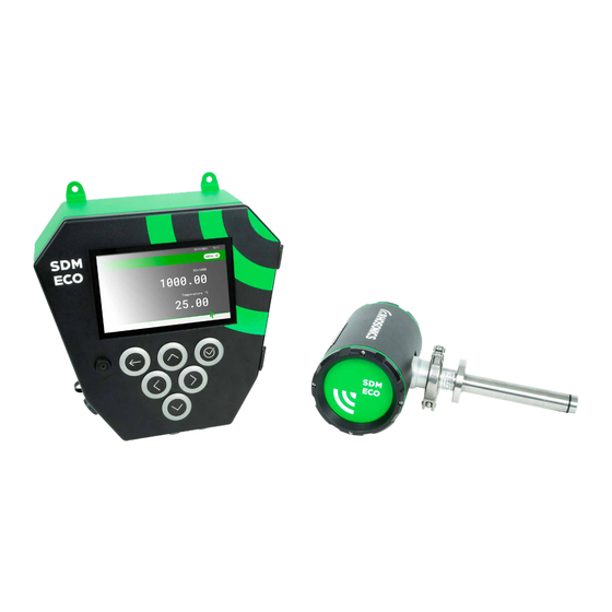
SDM ECO – Slurry Density Meter ECO 1.6.1 SDM ECO The SDM ECO (Figure 1-1) consists of a SDM ECO transmitter with sensor and a SDM ECO HMI. Figure 1-1: SDM ECO 1.6.2 Transmitter The transmitter (Figure 1-2) (full name: SDM ECO transmitter) is the cylindrical housing which can be connected to the sensor. -
Page 12: Sensor
SDM ECO – Slurry Density Meter ECO 1.6.3 Sensor The sensor (Figure 1-3) (full name: SDM ECO sensor) is the elongated metal cylinder which can be connected to the transmitter. Figure 1-3: Sensor 1.6.4 HMI The HMI (Figure 1-4) is the metal housing with the display and buttons. - Page 13 The identification plate (Figure 1-6, pos. 1) of the HMI is mounted on one of the sides of the HMI. Figure 1-6: Identification plate HMI Write down the information of the two identification plates in this manual. Rhosonics needs these numbers when ordering parts and / or when help is needed from Rhosonics. www.rhosonics.com...
-
Page 14: Introduction
SDM ECO – Slurry Density Meter ECO INTRODUCTION In this introduction, you can find general information on: • Intended and non-intended use of the slurry density meter (SDM ECO); • Lifespan of the product; • Product specifications of the product. -
Page 15: Product Specifications
HOSONICS ODIFICATIONS WITHOUT CONSULTATION CAN LEAD TO LIFE THREATENING SITUATIONS Spare parts must always meet the technical specifications as laid down in the SDM ECO spare parts list. If in doubt, consult Rhosonics. Product specifications The product specifications of the SDM ECO can be found below. -
Page 16: Transmitter
SDM ECO – Slurry Density Meter ECO 2.4.4 Transmitter Figure 2-1: Transmitter housing dimensions PROPERTY VALUE Dimensions transmitter housing Ø170x212 mm (ØxL) Power supply Via PoE (Power over ethernet) Cable entries 1x M20x1.5, 1x M25x1.5 split cable gland for ethernet cable Ambient temperature -5°C to +50°C... -
Page 17: Hmi
SDM ECO – Slurry Density Meter ECO PROPERTY COMPOSITION / NORM Max pressure 16 bar (see graph below) Temperature range 0°C to 110°C (32°F to 230°F) (see graph below) Body materials Duplex 2205, SS316L Wetted materials Ceramics, Duplex 2205 Sensor surface radius... - Page 18 SDM ECO – Slurry Density Meter ECO PROPERTY VALUE Power supply 18 – 32 VDC Communication and output 2x 4-20mA, 1x RS485 with Modbus communication, 1x ethernet Data logging Continuous, retrievable via USB stick Cable entries 2x M20X1.5, 1x M25x1.5 split cable gland for ethernet, 1x M16x1.5 Ambient Temperature -5°C to +50°C (23°F to 122°F)
-
Page 19: General Description
SDM ECO – Slurry Density Meter ECO GENERAL DESCRIPTION The slurry density meter ECO (SDM ECO) is a product that is used to measure the density of slurry that flows through pipe systems. Its main components are: • a transmitter;... - Page 20 SDM ECO – Slurry Density Meter ECO Figure 3-2: Sensor sealings Legend Rubber sealing for sensor contact O-ring sealing flange O-ring for sensor flange Figure 3-3: HMI Legend Transparent protective display cover Buttons USB-port Cable glands at cable entry Split cable gland for ethernet cable...
- Page 21 SDM ECO – Slurry Density Meter ECO Figure 3-4: HMI control buttons Legend Confirm button Navigation buttons Back button Figure 3-5: HMI internal connectors Legend RS485 connector SD card input USB connector (for the USB connection/terminal on the outside of the HMI)
-
Page 22: Components Functionality
SDM ECO – Slurry Density Meter ECO Components functionality The sensor surface (Figure 3-6, pos. 3) connects to components within the transmitter (Figure 3-6, pos. 1) for processing measurements. The tri-clamp (Figure 3-6, pos. 8) is pre-assembled and connects the sensor (Figure 3-6, pos. -
Page 23: Pipe Integration Systems
SDM ECO – Slurry Density Meter ECO Figure 3-7: Components HMI Pipe integration systems To use the SDM ECO, it needs to be integrated within a pipe system. Several pipe integration systems are available. To get information on the best suited pipe integration system, contact Rhosonics. - Page 24 When the SDM (Figure 3-8, pos. 4) is correctly mounted onto the receiving adapter, the sensor surface will lay flush with the inner diameter of the connected pipes. This ensures reliable and consistent measurements. Figure 3-8: Example of a SDM ECO integrated within a vertical pipe system Legend Pipe...
-
Page 25: Safety
Always wear personal protective equipment (PPE), see chapter 4.3 below for a list of PPE. • Do not use the SDM ECO as a step, storage space or tool other than its intended use. • If you suspect the SDM ECO has previously been misused, arrange for an inspection by a qualified expert. -
Page 26: Warning Symbols On/Near The System
Always comply with safety instructions and hazard warnings. Always ensure that safety instructions and hazard warnings are well looked after and legible. When working with the SDM ECO, a number of warning and prohibition symbols might present themselves on pipes and/or equipment surrounding or near the SDM ECO. -
Page 27: Temperature Ranges
FROSTBITE BY WEARING SUITABLE CLOTHES SHOES GLOVES AND HEAD PROTECTION The SDM ECO can operate safely with the following temperature ranges: PROPERTY TEMPERATURE RANGE IN °C TEMPERATURE RANGE IN °F Environmental temperature when in use -5 °C to +50 °C 23 °F to 122 °F... -
Page 28: Preparations Working Area
SDM ECO – Slurry Density Meter ECO Preparations working area WARNING EEP THE WORKSPACE AS CLEAN AND SAFE AS POSSIBLE TO PREVENT ACCIDENTS AND DANGEROUS SITUATIONS To prevent accidents and dangerous situations, it is very important that the working area is very well looked after: •... -
Page 29: Installation
SDM ECO – Slurry Density Meter ECO INSTALLATION Supplies and items for installation CAUTION F ANY OF THE BASIC SUPPLIES DELIVERED BY HOSONICS ARE DAMAGED OR COMPROMISED CONTACT HOSONICS FOR REPLACEMENTS OR FURTHER INSTRUCTIONS EVER USE DAMAGED SUPPLIES NOTE SDM ECO... - Page 30 SDM ECO – Slurry Density Meter ECO Legend 1x O-ring for sensor flange 1x Sealing for sensor contact 10x Washers for sensor flange 10x Bolts for sensor flange 1x Yellow protection cover 1x Black protection cover for sensor 10m Ethernet cable...
-
Page 31: Guidelines For Vertical Pipe Mountings
• The SDM ECO must be placed in a vertical pipe at an straight (90°) angle in relation to the connected horizontal pipe (Figure 5-2). Vertical pipe mounting only results in reliable measurements if the flow goes in upstream direction. -
Page 32: Mounting The Pipe Integration System
(Figure 5-3); • The SDM ECO must be installed either on the left or the right side of the pipe. Figure 5-3: Horizontal pipe mounting example Mounting the pipe integration system... - Page 33 SDM ECO – Slurry Density Meter ECO CAUTION ATING COMPONENTS SHOULD BE CHECKED TO ENSURE THAT TOLERANCES AND COUPLINGS ARE COMPATIBLE O NOT USE PARTS THAT LOOK IRREGULAR OR DO NOT FIT PROPERLY ONTACT THE APPROPRIATE MANUFACTURER OF THE PRODUCT IN QUESTION TO...
-
Page 34: Installation Of The Sdm Eco
SDM ECO – Slurry Density Meter ECO PIPE INTEGRATION SUITABLE PIPE TYPE SYSTEM UWC wafer - Pipes 4” - 60” - UHPE - 316 - 304 - 904 Figure 5-7: UWC Wafer Clamp-in - For every pipe material - OD pipe Ø88-365 mm... -
Page 35: Nstalling The Sdm
SDM ECO – Slurry Density Meter ECO Figure 5-9: Receiving flange of pipe integration system 3. Make sure that the SDM ECO and its installation materials are complete, clean and undamaged. 5.5.2 Installing the SDM CAUTION HE CONTACTS OF THE SENSOR ARE SENSITIVE AND MUST ALWAYS BE PROTECTED... - Page 36 SDM ECO – Slurry Density Meter ECO Figure 5-10: Black protective cap CAUTION EVER REUSE OLD RINGS OR SEALINGS OR USE OTHER PRODUCTS THAN THE ONES SDM ECO. O SUPPLIED WITH THE NLY NEW RINGS AND SEALINGS SUPPLIED BY HOSONICS ARE SUITABLE FOR THE USED CHEMICALS AND LOCAL TEMPERATURES 4.
- Page 37 SDM ECO – Slurry Density Meter ECO 6. Gently slide the SDM ECO as straight as possible into the pipe integration system and align the screw holes of both flanges (Figure 5-12, pos. 1). Choose the position in such a way that cable glands point downwards.
-
Page 38: Preparing The Hmi Installation
SDM ECO – Slurry Density Meter ECO Figure 5-14: Crosswise tightening 5.5.3 Preparing the HMI installation Choose a location that: • provides easy access to the display for reading measurements or for configuration or calibration purposes; • is in a location with little or no risk of (heavy) working equipment damaging the HMI. - Page 39 SDM ECO – Slurry Density Meter ECO Ensure that no power is applied to the HMI when installing it. 2. Place the washers onto the bolts and keep them within reach. 3. Take measurements and drill holes that correspond with the HMI’s attachment points (Figure 5-15, pos.
-
Page 40: Connecting The Sdm Eco
SDM ECO – Slurry Density Meter ECO Connecting the SDM ECO Before connecting the SDM ECO, make sure that all supplies match the requirements as stated in the table in chapter 5.6.1. 5.6.1 Power supply requirements ITEM VALUE PoE cable... - Page 41 HE SPLIT CABLE GLAND IS A PLASTIC OBJECT THAT ONLY NEEDS TIGHTENING BY HAND 3. Remove the split cable gland for ethernet cable (Figure 5-18, pos. 1) from the SDM ECO transmitter by unscrewing it. Figure 5-18: Split cable gland 4.
-
Page 42: Connecting The Hmi
SDM ECO – Slurry Density Meter ECO Figure 5-19: SDM ECO ethernet connector 11. Tighten the split cable gland (Figure 5-18, pos. 1) to prevent moisture and dirt entering the SDM ECO. 12. Apply cable management to the ethernet cable so that no loose cable remains. -
Page 43: Power Supply Requirements
SDM ECO – Slurry Density Meter ECO 5.7.1 Power supply requirements ITEM VALUE Input voltage 18 - 32 VDC 5.7.2 Connecting the power cable DANGER LWAYS MAKE SURE THAT POWER CABLES ARE NOT CONNECTED TO A POWER SUPPLY WHILE CREATING NEW CONNECTIONS... - Page 44 SDM ECO – Slurry Density Meter ECO 2. Loosen a cable gland and guide the power cable through (Figure 5-22, pos. 1). Figure 5-22: Cable gland for power cable 3. Connect the power cable to the HMI power connector (Figure 5-23, pos. 1).
-
Page 45: Connecting Ethernet Cables
SDM ECO – Slurry Density Meter ECO 5.7.3 Connecting ethernet cables DANGER LWAYS MAKE SURE THAT POWER CABLES ARE NOT CONNECTED TO A POWER SUPPLY WHILE CREATING NEW CONNECTIONS CONNECT THE POWER SUPPLY AFTER CONNECTIONS HAVE BEEN SAFELY MADE AND THE CABLE COMPARTMENT IS SAFELY... - Page 46 ETHERNET CONNECTOR FOR THE TYPE OF CONNECTION YOU ARE ESTABLISHING 8. Connect the ethernet cable to one of these ethernet connectors: • SDM ECO transmitter PoE connector (Figure 5-26, pos. 2); • Webserver ethernet connector (Figure 5-26, pos. 1). Figure 5-26: HMI ethernet connectors 9.
-
Page 47: Connecting The Rs485 Or 4-20Ma Cables
SDM ECO – Slurry Density Meter ECO 10. Close and lock the HMI door. 11. Tighten the split cable gland for ethernet cable (Figure 5-24, pos. 1) to prevent moisture and dirt entering the HMI. 5.7.4 Connecting the RS485 or 4-20mA cables... - Page 48 SDM ECO – Slurry Density Meter ECO Unlock (Figure 5-22, pos. 2) and open the HMI door (Figure 5-27). Figure 5-27: Opened door HMI 2. Guide the 4-20mA and/or RS485 cables each through a free cable gland (Figure 5-28, pos. 1).
- Page 49 SDM ECO – Slurry Density Meter ECO RS485 GND 2. A = RX+ 3. B = RX- 4. A (Rt) 5. B (Rt) 6. Y = TX+ 7. Z = TX- 8. RS485 GND Figure 5-29: HMI 4-20MA (2x) and RS485 connector (with legend) 4.
-
Page 50: Operation
SDM ECO display and buttons 6.2.1 Accessibility and functionality The SDM ECO display and its buttons support several access level functionalities. Setting time and date, setting the log interval and a minor system status icon displays the most relevant error in case of measurement problems. -
Page 51: Symbols, Buttons And Icons
SDM ECO – Slurry Density Meter ECO 6.2.2 Symbols, buttons and icons During operation, several items can be visible on the display (Figure 6-1). ITEM / ICON EXPLANATION LOCATION ON SCREEN Top right corner on main Access main menu screen... -
Page 52: Tatus Sdm Eco And Display Colors
Figure 6-1: Display with icon positions 6.2.3 Status SDM ECO and display colors The status of the SDM ECO is shown through different icons and backlight colors. Time-out mode is optional. The screen has two modes: active and time-out. The active mode is activated by pressing a button. - Page 53 Green Status: Normal operation Status: Normal operation Output: Valid Output: Valid Info: Device is operating within specified Info: Device is operating within specified range. range. Table 6-2: SDM ECO states and modes - Green colored www.rhosonics.com SDM ECO Manual v2.0...
- Page 54 Maintenance is required. Info: Maintenance is required. Color: Color: Status: Failure Status: Failure Output: Invalid Output: Invalid Info: Replace device. Info: Replace device. Table 6-3: SDM ECO states and modes – Yellow, blue and red colored www.rhosonics.com SDM ECO Manual v2.0...
-
Page 55: Operation Via Sdm Eco Display And Buttons
6.3.1 Power on the SDM ECO To power on the SDM ECO, press the two buttons below for 6 seconds. The screen will blink. Release the buttons and wait for the device to power on. This can take 60 seconds. -
Page 56: Home Page
6.3.2 Home page The first page seen when the SDM ECO is starting up is the Software Page, see Figure 6-6 on page 72. When a key is pressed in time-out mode, the Home Page will be shown. The Home Page contains measurement values. -
Page 57: Main Menu
SDM ECO – Slurry Density Meter ECO 6.3.3 Main menu On the Home Page press to go to the Main Menu. In the Main Menu you can choose from these options: • Settings • Calibration • Diagnostics • Factory 6.3.4 Settings Main Menu ->... -
Page 58: Language
SDM ECO – Slurry Density Meter ECO 6.3.5 Language Main Menu -> Settings -> Language. Select a language. 6.3.6 Backlight Main Menu -> Settings -> Backlight. On the SDM ECO you can set Backlight brightness. www.rhosonics.com SDM ECO Manual v2.0... -
Page 59: Ranging
Main Menu -> Settings -> Ranging. On the SDM ECO you can set Ranging. On this page the upper and lower range value can be set for two analog outputs. Adjusting output mA range is used to assign which value is corresponding to the 4mA and 20mA range of the analog output. -
Page 60: Restart
With the Restart option, the SDM ECO will be rebooted. 6.3.10 Shutdown Main Menu -> Settings -> Shutdown. With the Shutdown option, the SDM ECO will be shut down. 6.3.11 Calibration Main Menu -> Calibration. Within the Calibration menu, several calibration options are available. This menu is protected with PIN access to prevent unauthorized use (PIN: 20488). -
Page 61: Multi-Point Calibration (Mpc)
SDM ECO – Slurry Density Meter ECO 6.3.12 Multi-point calibration (MPC) Main Menu -> Calibration -> SG -> Water calibration. See chapter 7.2: Multi-point calibration for multi-point calibration. 6.3.13 Temperature NOTE OR DETAILED INSTRUCTIONS ON HOW TO RETRIEVE THE MENTIONED VALUES FOR A... -
Page 62: Decay Time
SDM ECO – Slurry Density Meter ECO 6.3.14 Decay Time Main Menu -> Calibration -> Decay Time. A Decay Time of 20 seconds is the default setting. This setting is sufficient for most applications. For a faster response time the Decay Time should be set lower, resulting in higher noise. -
Page 63: Reset Calibration
SDM ECO – Slurry Density Meter ECO 6.3.16 Reset Calibration CAUTION EAD THIS SECTION CAREFULLY BEFORE STARTING AY ATTENTION BEFORE PRESSING RESET F ACCEPTED ALL CALIBRATIONS WILL BE LOST AND RESET TO FACTORY SETTINGS Main Menu -> Calibration -> Reset calibration. -
Page 64: Diagnostics
SDM ECO – Slurry Density Meter ECO 6.3.17 Diagnostics Main Menu -> Diagnostics. Within the Diagnostics menu, several diagnostic options are available to have a closer look at issues and performances. This menu is protected with PIN access to prevent unauthorized use (PIN: 20488). -
Page 65: Logging
DATA ENTRIES Main Menu -> Diagnostics -> Logging. The SDM ECO is constantly logging. This has the advantage that the log can be accessed after an incidental measurement error. When starting a test, it may be necessary to clear the log data. -
Page 66: Sensor
SDM ECO – Slurry Density Meter ECO 6.3.21 Sensor Main Menu -> Diagnostics -> Sensor. On this page you will find information on the sensor settings. Optionally, new sensor setting can be loaded, see chapter 6.4.3. 6.3.22 Plots Main Menu -> Diagnostics -> Plots. -
Page 67: Date & Time
SDM ECO – Slurry Density Meter ECO 6.3.23 Date & time Main Menu -> Diagnostics -> Date & time. Although the time and date are set automatically, errors might occur. Within the menu Date & time, these values can be set. Please set to the local date and time. The timestamps are used in calibration, troubleshooting and to interpret the log files. -
Page 68: Factory
HMI USB-port (Figure 6-2, pos. 1) is located on the bottom side of the HMI; • a SDM ECO USB-port (Figure 6-3, pos. 1) is located behind the front lid of the SDM ECO. Figure 6-2: HMI USB-port The HMI USB-port is used for: •... -
Page 69: Updating The Hmi Software Via Usb
SDM ECO – Slurry Density Meter ECO Figure 6-3: SDM ECO USB-port The SDM ECO USB-port is used for updating software transmitter. 6.4.1 Updating the HMI software via USB To update the software on the HMI: On the HMI, choose: Main Menu -> Diagnostics -> Update. -
Page 70: Load Sensor Settings
Saving settings and logging can be done for diagnostics evaluation and for troubleshooting. When a log-file is stored to the USB stick the settings from the SDM ECO will be stored as well. The settings from the SDM ECO can then be interpreted by the factory. -
Page 71: Pdating The Sdm Eco Software Via Usb
4. Insert an USB stick into the USB connector (Figure 6-5, pos. 1) with the latest software. Figure 6-5: SDM ECO USB connector 5. Power on the SDM ECO by restoring the power supply. 6. Wait a few minutes. www.rhosonics.com... -
Page 72: Checking The Software Version
SDM ECO – Slurry Density Meter ECO Disconnect the USB stick. Place the frontal lid. Tighten the 4 socket head screws (Figure 6-4, pos. 1) on the outer side of the frontal lid. Checking the software version To check the software version: On the HMI, select Main Menu ->... -
Page 73: Calibration
SDM ECO – Slurry Density Meter ECO CALIBRATION CAUTION SDM-SG SDM-SG MUST BE CALIBRATED FOLLOWING THE CALIBRATION METHOD SDM-WT% SDM-WT% MUST BE CALIBRATED FOLLOWING THE CALIBRATION METHOD IXING UP CALIBRATION METHODS WILL RESULTS IN INCORRECT READINGS How ultrasonic sound is transformed into density values The density of slurry is measured through acoustic impedance, see Figure 7-1. -
Page 74: Mpc Gui Interface
SDM ECO – Slurry Density Meter ECO MPC GUI interface 7.3.1 Used profile The used profile is the profile used for calculating SG. By default and until another profile is created, it is the water profile, which is a system-managed profile. -
Page 75: Liquid Profiles Homepage
SDM ECO – Slurry Density Meter ECO NOTE EMPERATURE MUST BE CALIBRATED TO PERFORM WATER CALIBRATION CORRECTLY NOTE AKE SURE NO BUBBLES ARE COVERING THE TIP OF THE SENSOR WHEN PUT IN DISTILLED WATER 7.3.3 Liquid profiles homepage After performing the system’s first water calibration, the liquid profile homepage becomes accessible. - Page 76 The next screen will ask you to insert a temperature range in which the liquid will be measured. That range will help the SDM ECO define how many calibration points are required to cover the temperature range, and at which temperature each calibration point should be sampled.
-
Page 77: The Profile Dashboard
SDM ECO – Slurry Density Meter ECO The following screen will show the amount of calibration points the SDM ECO recommends you to perform, based on the given temperature range. Here you can either agree to the recommendation or set the amount of calibration points manually. -
Page 78: Sampling A Calibration Point
SDM ECO – Slurry Density Meter ECO From this dashboard you can perform operations relevant to the calibration points: • sample the calibration points; • remove a calibration point (for example, in case of bad sampling); • add a calibration point (up to 5);... - Page 79 SDM ECO – Slurry Density Meter ECO The sampling process should take about 10-50 seconds, depending on MPC settings. After completing the sampling process, the next screen will show the sample temperature. Click the ‘Complete’ button. A new screen will appear. In order to complete the calibration point’s calibration you have to test the density of your gathered sample with the noted temperature, and fill it in.
-
Page 80: Using An Available Profile
SDM ECO – Slurry Density Meter ECO NOTE OU CAN DECIDE TO ENTER THE DENSITY VALUE LATER FOR EXAMPLE IN CASE THE DENSITY IS YET UNKNOWN In case you decide to enter the density at a later time, you can always return to this screen from the profile’s dashboard, by selecting ‘Fill density’. - Page 81 SDM ECO – Slurry Density Meter ECO The following screen lists all ready profiles. You can now select the profile to be used. Once selected, the used profile will appear on the liquid profiles homepage screen, and will be used for SG calculations.
-
Page 82: Configure And Use The Super Profile
SDM ECO – Slurry Density Meter ECO 7.3.8 Configure and use the super profile The super profile feature enables you to merge multiple user profiles into a single unified profile. This eliminates the requirement to switch between different user profiles each time the liquid being measured changes. - Page 83 SDM ECO – Slurry Density Meter ECO NOTE NCLUDED PROFILES ARE USED TO CREATE THE SUPER PROFILE WHILE EXCLUDED PROFILES ARE NOT In the following example, there are 3 different user liquid profiles. The first one is excluded from the super profile, the second one is included and the third one is not a ready profile –...
-
Page 84: Webserver Interface
SDM ECO – Slurry Density Meter ECO Webserver interface The webserver is another method to interact with MPC. It enables you to: • perform basic operations; • change profile names to prevent confusion; • identify profiles. Below is an example of the webserver homepage with a clear reading of the current SG and temperature measurements. -
Page 85: Renaming A Profile
SDM ECO – Slurry Density Meter ECO To select a different profile: Open the drop-down menu. Select a different profile. Click the ‘Apply’ button. 7.4.2 Renaming a profile To rename a user profile: Navigate to the calibration tab. Select ‘SG’ on the side panel. -
Page 86: Editing The Super Profile
SDM ECO – Slurry Density Meter ECO 7.4.3 Editing the super profile To include or exclude ready profiles from the super profile, you should select ‘Edit super profile’ from the SG calibration page. To edit the super profile: Navigate to the calibration tab. -
Page 87: Maintenance
‘R ’. MANUAL HOSONICS SAMPLING PROCEDURE 3. Check the SDM ECO values. Take reference samples during a stable process / reading. Consult the manual ‘Rhosonics sampling procedure’. In case of a deviation, take the following actions: • check the process temperature. Validate the set temperature of the SDM ECO;... -
Page 88: Detailed Maintenance Tasks
SDM ECO – Slurry Density Meter ECO Detailed maintenance tasks The SDM ECO needs detailed maintenance every 3 – 6 months for the: • tri clamp, see chapter 8.2.1; • transmitter and sensor connections, see chapter 8.2.2; • sensor, see chapter 8.2.3;... -
Page 89: Transmitter And Sensor Connections
SDM ECO – Slurry Density Meter ECO 8.2.2 Transmitter and sensor connections CAUTION E AWARE THAT THE TRANSMITTER AND SENSOR CONNECTIONS ARE FRAGILE To check and maintain the transmitter and sensor connections: Disconnect the transmitter from the power supply. 2. Remove the ethernet cable (Figure 8-3, pos. 1). - Page 90 (Figure 8-5, pos. 3) and small notch (Figure 8-5, pos. 4). Figure 8-5: Sensor contact pins 8. If the SDM ECO remains disassembled; protect the sensor or transmitter: • place a yellow protection cap (Figure 8-6, pos. 1) on the transmitter;...
- Page 91 SDM ECO – Slurry Density Meter ECO Figure 8-6: Yellow protection cap on transmitter Figure 8-7: Yellow protection cap on sensor www.rhosonics.com SDM ECO Manual v2.0...
- Page 92 SDM ECO – Slurry Density Meter ECO 9. If the SDM ECO needs to be re-assembled, make sure that the 2 sealings are present in the transmitter and sensor, see Figure 8-8, pos. 1 and 2. Figure 8-8: Sensor sealings 10.
-
Page 93: Sensor
SDM ECO – Slurry Density Meter ECO 8.2.3 Sensor NOTE SDM ECO 8-9, . 2), EFORE REMOVING THE FROM THE INSTALLATION IGURE MARK 8-9, . 1). T THE POSITION OF THE SENSOR ON THE FLANGES IGURE HE SENSOR MUST 8-9, . - Page 94 SDM ECO – Slurry Density Meter ECO 3. Support the transmitter by hand. NOTE E AWARE THAT THE TRANSMITTER WEIGHTS APPROXIMATELY HE TRANSMITTER WILL DETACH FROM THE SENSOR WHEN THE TRI CLAMP IS LOOSENED 4. Loosen the nut of the tri clamp (Figure 8-11, pos 1).
- Page 95 SDM ECO – Slurry Density Meter ECO 6. Remove the bolts and washers (Figure 8-12, pos. 1). Figure 8-12: M5 bolts and washers 7. Remove the sensor from the pipe integration system. NOTE E AWARE TO ONLY ROTATE THE SENSOR IN CLOCKWISE DIRECTION 8.
- Page 96 SDM ECO – Slurry Density Meter ECO NOTE N DOUBT OF THE CONDITION TAKE PICTURES AND CONTACT HOSONICS 9. Place back the sensor in the exact same position (Figure 8-14, pos. 3). Figure 8-14: Sensor position markings NOTE HEN PLACING BACK THE SENSOR...
- Page 97 SDM ECO – Slurry Density Meter ECO 12. Make sure that the 2 sealings are present in the transmitter and sensor (Figure 8-15, pos. 1 and 2). Figure 8-15: O-rings 13. Place the transmitter back on the sensor. 14. Place and tighten (crosswise) (Figure 8-16, pos. 1) the bolts and washer at 4.2 Nm (8x).
-
Page 98: Sensor Settings
Sessionsetting.json file has the same software version as the SDM ECO transmitter: o check the current software version of the SDM ECO transmitter, see chapter 6.5. For rebooting see chapter 6.3.8. o Check the software version of the file. Open the Sessionsetting.json file from the supplied USB stick in excel. -
Page 99: Troubleshooting
SDM ECO – Slurry Density Meter ECO TROUBLESHOOTING The SDM ECO is designed to work maintenance free for a long time. Of course, as in every technical unit, an issue may occur. Here are some tips on how to find a solution. If this does not solve your problem or if your problem is not listed, contact Rhosonics. -
Page 100: Issues And Solution
SDM ECO – Slurry Density Meter ECO Issues and solution The most common SDM ECO issues and their problems are listed below: Issue Possible cause Possible solution Display is black / off. No power. Check power supply, see chapter 5.6.1. - Page 101 SDM ECO – Slurry Density Meter ECO Issue Possible cause Possible solution SDM ECO shows a yellow Value is out of range due to Change SDM ECO 4-20 mA screen with a question incorrect 4-20 mA setting. output to same 4-20 mA marker.
- Page 102 SDM ECO – Slurry Density Meter ECO Issue Possible cause Possible solution Check the sensor, see Sensor is worn out. chapter 8.2.3. Calibration is incorrect. Calibrate the SDM ECO, see chapter 7. Sensor has (strange) Sensor was installed Gather information and wear/abrasion.
- Page 103 SDM ECO – Slurry Density Meter ECO Issue Possible cause Possible solution SDM ECO value is drifting of Calibrate the SDM ECO, see Incorrect calibration. over time. chapter 7. Sensor is worn out. Remove sensor and check on wear / abrasion, see chapter 8.2.3.
-
Page 104: Resistance Check
SDM ECO – Slurry Density Meter ECO 9.2.1 Resistance check To measure the resistance of the transmitter and sensor: Remove the split cable gland (Figure 9-1, pos. 1). Make sure to not damage the ethernet cable. Figure 9-1: Cable gland for PoE cable 2. - Page 105 SDM ECO – Slurry Density Meter ECO 5. Measure the resistance of the transmitter connection points. The resistance is overload. Measure between the inner and outer connection point (Figure 9-2, pos. 1 and 2). Figure 9-3: Transmitter connection 6. Measure the resistance of the sensor connection pins. The resistance is overload. Measure between the inner and outer connection pin (Figure 9-3, pos.
- Page 106 Measure between the inner connection point (Figure 9-4, pos. 1) and the end of the sensor (Figure 9-4, pos. 1 and 2). Figure 9-5: Sensor connections for resistance measurement 8. Contact Rhosonics if the resistance is not correct. www.rhosonics.com SDM ECO Manual v2.0...
-
Page 107: Red Screen
SDM ECO – Slurry Density Meter ECO 9.2.2 Red screen NOTE 6.2.3. OR MORE INFORMATION ABOUT THE RED SCREEN SEE CHAPTER A red screen indicates a problem with the transmitter or the sensor, see Figure 9-6. Figure 9-6: Red screen To solve the red screen: Check if the tri clamp is installed properly. -
Page 108: Yellow Screen
SDM ECO – Slurry Density Meter ECO 9.2.3 Yellow screen NOTE 6.2.3. OR MORE INFORMATION ABOUT THE YELLOW SCREEN SEE CHAPTER The measured density is lower or higher than the set 4-20mA value, see Figure 9-6. Figure 9-8: Yellow screen To solve the yellow screen: Check the process conditions. -
Page 109: Frequently Asked Questions
SDM ECO (ID plate), see chapter 1.7. How do I perform a software update? See chapter 6.4.1. How to get the log file from the SDM ECO? See chapter 6.4.2. How much data points can the SDM ECO 65 535 entries. - Page 110 • process conditions. This means the more accurately you work with the SDM ECO, the better results will be achieved. What kind of USB stick do I need to use? USB stick with: •...
-
Page 111: Transport And Storage
11.1 Transport When transporting the SDM ECO, the SDM ECO must be safely packed into a strong box – preferably in its original box - that protects it from outside moisture and dust. Make sure to add material inside the box and around the SDM ECO that protects it from damage in case the box bumps or drops. -
Page 112: Disposal
SDM ECO – Slurry Density Meter ECO DISPOSAL When disposing the SDM ECO after its use, it can be sent to Rhosonics for proper disposal. It is the user’s responsibility to safely ship the SDM ECO to Rhosonics. The shipping address of Rhosonics is mentioned on the last page of this manual. -
Page 113: Appendices
SDM ECO – Slurry Density Meter ECO APPENDICES 13.1 List of spare parts DESCRIPTION PART NUMBER CONSISTS OF SDM ECO Sensor only (no SDM ECO Sensor SDM ECO Sensor transmitter included) - spare part SDM ECO transmitter SDM ECO transmitter... -
Page 114: List Of Options
SDM ECO – Slurry Density Meter ECO 13.2 List of options DESCRIPTION PART NUMBER CONSISTS OF Blind Plug (for the BP-60T13-HDPE- HDPE blind plug 16-146 mm with installation tool) UNIVERSAL-VITON 1 x O-ring Viton® 51414 Ø20,3x2,62 and 1 x O-ring 29.82x2.62 Viton 80S Table 13-2: List of options www.rhosonics.com... -
Page 115: Menu Tree
SDM ECO – Slurry Density Meter ECO 13.3 Menu tree → Settings ·················· → Language ···························· → English ············ → Spanish ············ → French ············ → Portuguese ············ → Backlight ············ → Ranging ································ → ············ → Temperature ············ → About us ············... -
Page 116: Appendix A: Sound Speed Of Water At To 100 °C
SDM ECO – Slurry Density Meter ECO 13.4 Appendix A: Sound speed of water at 0 to 100 °C T [°C] c [m/s] T [°C] c [m/s] T [°C] c [m/s] T [°C] c [m/s] 1402.388 1496.687 1542.551 1555.133 1407.367 1499.323... -
Page 117: Appendix B: Density Of Water At To 100 °C
SDM ECO – Slurry Density Meter ECO 13.5 Appendix B: Density of water at 0 to 100 °C T [°C] RHO [g/l] T [°C] RHO [g/l] T [°C] RHO [g/l] T [°C] RHO [g/l] 999.86341 997.04784 988.00825 974.85658 999.91390 996.78615 987.55238...
Need help?
Do you have a question about the SDM ECO and is the answer not in the manual?
Questions and answers