
Related Manuals for Rhosonics 9670


Summary of Contents for Rhosonics 9670
- Page 1 Model 9670 Ultrasonic TSS and TDS Model 9670 Analyzer Ultrasonic Suspended Solids (TSS) and dissolved solids (TDS) Analyzer MANUAL Software Version: 2.2.7 Date: 8 December, 2009 Page 1/46...
-
Page 2: Table Of Contents
TABLE OF CONTENTS PREFACE URPOSE YMBOLS AND CONVENTIONS BOUT THIS MANUAL 1.3.1 ONVENTIONS INSTALLATION NTRODUCTION NALYZER INSTALLATION 2.2.1 PLIT TYPE INSTALLATION 2.2.2 EATHER PROOF HOUSING INSTALLATION ENSOR INSTALLATION NSTALLING THE CABLES CONFIGURATION. NTRODUCTION 3.1.1 OUCH CREEN UNCTIONS 3.1.2 REPARATIONS NALOG UTPUT CONFIGURATION 3.2.1 ROCEDURE... - Page 3 LIQUID SELECTION AND EDITING IQUID PRODUCT SELECTION 4.1.1 URPOSE 4.1.2 ROCEDURE MANUAL SELECTION 4.1.3 ROCEDURE REMOTE SELECTION DITING LIQUIDS POLYNOMIAL CALIBRATIONS 4.2.1 NTRODUCTION 4.2.2 URPOSE 4.2.3 REPARATION FOR EDITING LIQUID PARAMETERS 4.2.4 ROCEDURE 4.2.5 DJUSTING INDIVIDUAL ALARM TRIP POINTS 4.2.6 DJUSTING POLYNOMIALS CALIBRATION YPES OF CALIBRATION...
-
Page 4: Preface
1.1 Purpose This manual explains the installation, configuration, operation and calibration of your Rhosonics Inline Process Analyzer. For ease of reading and understanding, the manual is organized in logical steps, divided over several chapters and sections. Where necessary, the manual provides additional information Software Version: 2.2.7... -
Page 5: Symbols And Conventions
about the above mentioned issues, and gives you all the answers regarding ultrasonic inline concentration analysis in the added section with Frequently Asked Questions. 1.2 Symbols and conventions The following words and symbols indicate special messages: WARNING: This symbol indicates that failure to follow directions in the warning could result in bodily harm. -
Page 6: Installation
/ aluminium housing. To prepare the installation, please refer to the figures below. Midden Engweg 37A Phone: +31 341 370073 NL-3882 TS Putten Fax: +31 341 370074 The Netherlands Email: info@rhosonics.nl Internet: www.rhosonics.nl Fuse Fuse 1.6A 3.15A Type:... - Page 7 +0.5 Figure 2: Panel cut-out for display installation 2.2.1.2 Touch Screen connections The touch screen has 2 major connections, i.e. the 24 Volt power supply, and the connection with the PCB control unit. The connection with 24VDC is realized through screw-type terminals. The connection with the PCB control unit must be established with the special cable.
-
Page 8: Weather Proof Housing Installation
WARNING: A TOO TIGHT FIT OF THE SCEEN MAY CAUSE DAMAGE AFTER INSTALLATION NOTE: There are two different types of displays, so the ports can be located at other places on the display than is shown in the drawing. 2.2.2 Weather proof housing installation SYSTEM Display Cable gland holes (5x) for... -
Page 9: Sensor Installation
Mains DC Power Ext. Hold Power Fuse Fuse 90-240 18-36 1.6A 3.15A Volt Volt slow slow Model Serial No. External Liquid select Control Communication Binary I/O RS 232 / Touch screen Ethernet 422 /485 RS 232/485 Density Touch meter screen Power supply I2C Density meter external devices... - Page 10 Temp. Density Factory calib. c alib. calib. About Assist Diagn. Rhosonics Analyzer Display Process pipe (Touch screen) with flow and ultrasonic cell 1 Ultrasonic coax cables 2 Cat 6 patch cable (no standard cable) Figure 6: Schematic cabling overview analyzer with ultrasonic cell NOTE: The ultrasonic sound path must be horizontal at all times.
- Page 11 NOTE: The ultrasonic sound path must be horizontal at all times. This implies that the transducers must be installed at either side of the pipe, NEVER on the top and bottom. Mains DC Power Power Ext. Hold Fuse Fuse 90-240 1.6A 3.15A 18-36...
-
Page 12: Configuration
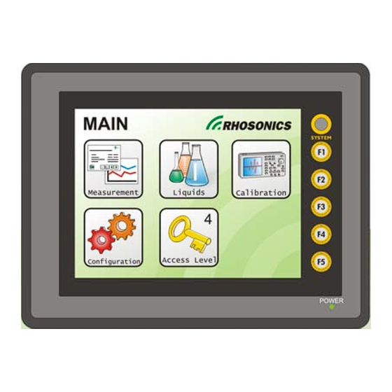
3. Configuration. Configuration can be done through the configuration menu, by pressing the exit icon on the main measurement screen: Figure 9: MAIN MENU page NOTE: The shown icons depend on your access level. 3.1 Introduction Once you have chosen the configuration mode, you will be able to establish specific operating parameters of the analyzer. -
Page 13: Analog Output Configuration
• What measured value (i.e. concentration) you wish to check. • Whether you wish to use 2 alarms for hi-hi lo-lo configuration. • If the analyzer is used for several different products: alarm trip points for each product. 3.2 Analog Output configuration This section describes how you can configure your 4~20mA outputs: With these settings, you can set the following: •... -
Page 14: Error Communication Through Analog Outputs
CAUTION: Scaling the output to a high range, i.e. 0~100 wt%, results in loss of accuracy. The accuracy of the output is 0,05 % of scale. Choosing a smaller range (difference between low and high value) results in a better resolution. In the above example, the accuracy of the output is 0,1% of (15-10), which equals 0,0025 wt%. -
Page 15: Display Configuration
“bulk” value of the liquid. When fast response is not required, we strongly recommend setting the τ63 time between 5 and 20 seconds. Since smoothing affects the response time, the best setting is a trade-off between accuracy and response time. A decay rate of 5 seconds is recommended for most applications. -
Page 16: Display Smoothing
► Press [2Digits] or [3 Digits] on the Resolution page (automatic return to the Display configuration page) 3.3.3 Display smoothing This setting is the same as the decay time for the analog outputs. The result is that concentration values are smoothened before they are sent to the output. A decay rate of 5 seconds is recommended for most applications. -
Page 17: Instructions
• From the main menu, choose Configuration – Sensor – US sensor • Check or modify the data as indicated on the data sheet NOTE: If a probe is replaced, the previous data sheet is no longer valid. 3.4.3 Instructions: ►... -
Page 18: Preparation
be possible. In addition, you may select whether the alarms are activated during fault conditions (Normal) or activated when no alarm is present (inverted operation). 3.5.2 Preparation. • Determine which value you wish to monitor with each alarm. • Determine whether you wish the alarm relay contacts to be activated during normal operation (no alarm) or during a fault condition. -
Page 19: Memory Stick Logging
• Use of the memory stick feature allows you to log measurement data • The memory stick can be used to download all settings of the analyzer • The memory stick can be used to download a typical waveform, which can be useful for trouble shooting •... - Page 20 The following table shows the data arrangement in the CSV-file on the USB stick. Value @ Normal Name Description operation Calculated value 1 (i.e. 0-100 %w/w, 0-350 g/l Polynoom 1 Concentration) Salt, etc. In between the Min. Temperature sensor 1 Temperature sensor 1 [°C] temp and Max.
-
Page 21: Verifying The Ultrasonic Signal Waveform
3.6.4 Verifying the Ultrasonic Signal Waveform 3.6.4.1 Purpose The purpose is to verify the proper operation of the analyzer with regard to the ultrasonic echo. Its visualized waveform (time vs. amplitude plot) can be an aid to identify problems which are related to the process (gas bubbles, faulty cable etc.) When you are asked by the factory or your sales agent to submit a waveform for diagnostics purposes, please follow this procedure. - Page 22 3.6.4.3 Examples of ultrasonics waveforms Please refer to the previous section for a general explanation. This echo is extremely good, as there is no noise before the echo (left = before). The system will measure the time based on the first negative going ½-period, which is clearly identifiable.
-
Page 23: Factory Diagnostics To Usb
For trouble shooting purposes, the factory or the service engineer of your sales representative may ask you to copy the factory settings to a USB stick and send these settings to Rhosonics. 3.6.5.2 Preparation. NOTE: Please read the previous section(s) to obtain information about the type of memory stick to be used. - Page 24 Each time, a unique image is stored in the \RHO\HDCOPY of the USB stick. By copying relevant pages, either during calibration or during operation, it will be easy to communicate specific pages of interest to the USB stick. Once you are done with copying display images to the USB stick, you may take out the stick and view the images on your PC, e-mail them to your service agent, etc.
-
Page 25: Liquid Selection And Editing
4. Liquid Selection and Editing 4.1 Liquid (product) selection 4.1.1 Purpose: To make one previously stored liquid calibration the new and active calibration. When your analyzer is used for one specific type of liquid only, the liquid select procedure may not be of interest to you. -
Page 26: Purpose
To restore field calibration data or duplicate field calibration data from other analyzers into this analyzer. • To edit polynomial constants according to Liquid Datasheet sent by Rhosonics 4.2.3 Preparation for editing liquid parameters • Obtain the liquid data sheet from the factory •... - Page 27 Changing polynomials may lead the incorrect concentrations. Only perform this action if Rhosonics asked you to do so. Rhosonics may send you a new Liquid Datasheet with new liquid polynomials to improve the concentration calculation. To enter the new polynomial values into a liquid follow the next steps.
-
Page 28: Calibration
5. Calibration You may calibrate the analyzer in order to assure optimal analysis results. This section describes the different calibration routines, and the intervals which are required. 5.1 Types of calibration The following table lists the different types of calibration, their purpose and the interval required to perform these calibrations. -
Page 29: Background And Functions Of Zero And Clear Liquid Calibration
5.2 Background and Functions of Zero and Clear Liquid Calibration. The Rhosonics Model 9670 analyzer works with special US sensors, which measure the following parameters by ultrasonic means: • Temperature • Internal transducer efficiency • External transducer efficiency (acoustic impedance) •... -
Page 30: Temperature Offset
Figure 27: CALIBRATION page 5.4 Temperature offset 5.4.1 Purpose To calibrate the ultrasonic temperature measurement. Only its offset is corrected, its span needs no calibration. 5.4.2 When needed It is necessary when you first connect the sensors to the analyzer. Also, when you swap the sensor on channel 1, it is necessary to recalibrate the temperature. -
Page 31: When Needed
The main purpose is to improve the accuracy of the TDS measurement. For this calibration we recommend using water with less than 0,2 x the accuracy you require. This calibration applies an adjustment factor to the sound path, as the sound speed of water is known to the analyzer at each temperature. -
Page 32: High Density Or Field Calibration
for water), as well as the amount of solids. These calibration constants are called certified temperature and certified TSS solids. The procedure can be done in water, when there is no way to calibrate under real process conditions. When you have done the calibration in water, SG reading, as well as the temperature need no further calibration. -
Page 33: Field (Sample) Calibration
► Press the Start button. The next menu indicates a counter that counts back from 60 seconds. Wait until it reads -1. The density will now be corrected within +/- 0.1 °C and the SG within +/- 0.1%. ► The correct factors are determined when the counter stops. Press OK (V). The density reading should be stable within +/- 1 g/l. -
Page 34: Automation And Communication
6. Automation and communication. The Rhosonics analyzer has several features to minimize operator interference. Most of them are related to remote product switching and regular calibration routines. CAUTION: Be aware that changing of any data can stop the communication. Do not change any data if you do not fully understand the effect of all actions to the performance of the analyzer. -
Page 35: External Hold Function
6.4 External Hold function 6.4.1 Purpose External HOLD is useful during product stand still. Due to the heating of the pipe, the temperature of the liquid may not be stable. The External Hold function will stop the measurement and freeze all outputs. 6.5 Automatic calibration 6.5.1 Auto dead time calibration The purpose of this feature is to reduce small errors, both operator and system errors. -
Page 36: Maintenance
Of the above measurements, the sound speed and the temperature may not be available. In fact, the Rhosonics Model 9620 analyzer does not use the sound velocity for analysis. The sound speed is depending on the DISSOLVED solids only, and NOT depending on the amount of total solids. -
Page 37: Ma Input Calibration
to Noise measured, due to S/N ratio. high. Check whether this message still Ratio This does NOT mean that is present with low concentrations. the attenuation cannot be This can mean cable or sensor failure. determined. Signal too Same as above Same as above large at start of echo... -
Page 38: Quick Trouble Shooting
► Press [Enter] (automatic return to the 4-20 mA OUT 1 calibration page 2) ► Press [Accept High] (automatic return to the 4-20 mA calibration page) NOTE: Repeat this procedure to calibrate 4-20 mA OUT2. Figure 28: 4-20 mA OUT 1 CALIBRATION page 1 7.1.5 Quick trouble shooting If anything fails, please take some time to follow the below trouble shooting list. -
Page 39: Frequently Asked Questions
8. Frequently asked questions 8.1.1 Installation questions Q: Do I need to calibrate the analyzer prior to installation? A: The analyzer has been calibrated and tested in the factory. There is no need to (re)calibrate the analyzer before installation, because all specific adjustments and calibrations can be done with a fully installed analyzer. - Page 40 Q: During certain process conditions, it can happen that gas bubbles are present in the liquid. How does this affect the measurement? A: The Rhosonics Ultrasonic Analyzer automatically detects the presence of product and gas bubbles. It will then freeze the measurement until a next valid measurement is possible. Due to its unique method of operation, the analyzer continues to operate reliably during upset process conditions.
-
Page 41: Technical Specifications
9. Technical specifications 9.1 Operation characteristics Temperature circuit: Resolution ± 0.001 °C (24 hours warm-up) Reproducibility ± 0.005 °C (24 hours warm-up) Range -10 °C through 110 °C Sound speed circuit: Resolution ± 0.002 m/s Reproducibility ± 0.01 m/s Range 200 m/s through 3000 m/s 4-20mA Outputs (2x): Resolution... -
Page 42: Environmental Conditions
9.4 Environmental conditions WARNING: To prevent electrical fire or shock hazards, do not expose the instrument to rain or excessive moisture. 9.4.1 Ingress Protection External touch screen display front side: IP65 (when using gasket) External touch screen display rear side: IP20 Control unit front side: IP20/55 Control unit rear side: IP20/24 Sensor: IP68... -
Page 43: Technology
10. Technology 10.1 Measurement sequence • Send pulse to transmitter • Receive echoes within echo window from receiver • Check validity of echo • Determine transit time and strength of echo • Measure temperature • Calculate sound speed • Calculate concentration 1 •... -
Page 44: Attenuation
TDS measurement as well as for correcting for changes in sound transfer (from sensor to liquid, as well as for beam spread loss). The Models 9630, 9660, 9670 and 9780 use a proprietary algorithm to measure the attenuation of the intensity of the sound waves, as well as to correct for the physical changes that cause the sound beam to attenuate. -
Page 45: Appendices
11. Appendices 11.1 Operating software structure for level 1, 2 and 3 in the Configuration menu Analog Configuration 4-20 mA IN Digital Calibration Temp. Sensor 1 Temperature Temp. Sensor 2 Sensor 1 Ultrasonic Sensor Sensor 2 Configuration Conductivity Calibration (Zero + Ref) Configuration Settings Density... -
Page 46: Options
• Fuses Ø5x20 mm, 3.15 A (18-30 VDC), slow-blow 11.3 Options No options 11.4 Appendix A: Sound speed of water at 0 to 100 °C T [°C] c [m/s] T [°C] c [m/s] T [°C] c [m/s] T [°C] c [m/s] 1402.388 1496.687 1542.551...
Need help?
Do you have a question about the 9670 and is the answer not in the manual?
Questions and answers